Learn about Ford F-250 / F-350 / F-450 / F-550 (1998-1999) fuse box and relay’s locations, functions, and maintenance tips for optimal vehicle electrical system.
The 1998–1999 model years mark a unique transition period for Ford’s heavy-duty trucks. In 1998, the F-250 and F-350 still used the older, pre-Super Duty body style, while 1999 introduced the all-new Super Duty lineup, including the F-450 and F-550 for the first time. Because of this shift, fuse box designs and relay locations can differ noticeably between these two years, even within the same model range.
Regardless of body style, fuses and relays serve the same essential purpose: protecting your truck’s electrical system from overloads and short circuits. When something electrical fails, dash lights, power windows, wipers, or the radio, checking the fuse box is always a smart first step before assuming a bigger problem.
This guide covers fuse box and relay locations for both the outgoing 1998 body style and the newly introduced 1999 Super Duty platform, along with safe access tips and how to use printed diagrams for identification.
MUST READ: DYI – How to Check Car Fuses?
(1998-1999) Ford F-250 / F-350 / F-450 / F-550 fuse box and relay with Diagram
WARNING
- Never replace a fuse with one that has a higher amperage rating.
- A fuse with a too-high amperage could damage the electrical part and cause a fire.
- On no account should fuses be repaired (e.g. patched up with tin foil or wire) as this may cause serious damage elsewhere in the electrical circuit or cause a fire.
- If a fuse blows repeatedly, do not keep replacing it. Instead, have the cause for the repeated short circuit or overload tracked and fixed.
- Terminal and harness assignments for individual connectors will vary depending on vehicle equipment level, model, and market.
Ford F-250 / F-350 / F-450 / F-550 (1998-1999) fuse assignment
Ford F-250 / F-350 / F-450 / F-550 Year of production: 1998, 1999
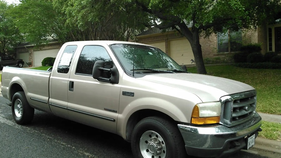
1998 Model Year: Fuse Box and Relay Locations (Pre-Super Duty Body)
If you own a 1998 F-250 or F-350, your truck shares much of its electrical layout with the 1992–1997 generation.
Interior Fuse Panel
The main fuse panel is located under the dashboard on the driver’s side, near the kick panel.
How to access it:
- Locate the panel cover beneath the dash, to the left of the steering column.
- Remove or flip down the cover, which is typically secured with clips or one to two screws.
- The fuse block is directly accessible once the cover is removed.
This panel controls interior circuits such as the dome light, radio, heater blower, and gauge cluster.
Engine Bay Relays
Like earlier OBS trucks, the 1998 model relies on individual relays mounted near the firewall and battery rather than a centralized relay box.
Common relay locations:
- Horn relay – near the firewall, driver’s side.
- Starter relay – near the battery or inner fender.
- Blower motor relay – near the heater box.
These relays plug directly into the wiring harness and can be pulled out for inspection without removing any covers.
1999 Model Year: Fuse Box and Relay Locations (New Super Duty Body)
The 1999 model year introduced a completely redesigned Super Duty platform, bringing a more organized electrical system with dedicated fuse boxes closer in structure to later Super Duty generations.
1. Engine Compartment Fuse Box (Power Distribution Box)
Located in the engine bay near the battery, this box centralizes many of the relays and high-amperage fuses that were previously scattered throughout the engine compartment on older models.
How to access it:
- Open the hood and locate the black plastic cover near the battery or firewall.
- Unclip or unscrew the cover, depending on configuration.
- Lift the cover to reveal the fuse and relay layout inside.
This box typically protects the cooling fan, headlights, starter circuit, and horn relay.
2. Interior Fuse Panel
The cabin fuse box is located under the dashboard, driver’s side, similar in position to the 1998 model but with a revised layout and labeling system to match the new electrical architecture.
How to access it:
- Locate the access panel to the left of the steering column.
- Remove the cover, usually secured by simple push clips.
- The fuse panel and a few mini-relays are visible once opened.
This panel handles interior accessories such as power windows, radio, wipers, and dashboard components.
3. Auxiliary Relay Box (Diesel and Upfitter Trucks)
Trucks equipped with the Power Stroke diesel engine or factory upfitter packages may include an additional relay box near the main engine bay fuse panel, housing relays for glow plugs, auxiliary lighting, or trailer functions.
How to Identify the Right Fuse or Relay
Both the 1998 and 1999 fuse panels include a printed diagram, either on the inside of the cover or molded into the panel itself, listing fuse numbers, amperage ratings, and circuit functions.
When troubleshooting:
- Match the malfunctioning component to its label on the diagram.
- Confirm the amperage rating before replacing any fuse.
- For relays, especially on the 1998 model without a centralized box, use a wiring diagram to confirm exact location and function, since relays can look nearly identical despite controlling different systems.
Safety Precautions Before Checking Fuses or Relays
- Turn off the ignition before accessing any fuse or relay.
- Disconnect the negative battery terminal for more involved work, especially near the starter relay or battery-adjacent components.
- Use a fuse puller or needle-nose pliers rather than metal tools to avoid sparking.
- Always replace a fuse with one of the same amperage rating to prevent wiring damage or fire risk.
- If a new fuse blows immediately, stop and inspect the circuit for a short instead of continuing to swap fuses.
- Given the age of these trucks, check for corroded connectors or brittle wiring insulation during inspection.
Checking and Replacing Fuses in Ford F-250 / F-350 / F-450 / F-550
If electrical components in the vehicle are not working, a fuse may have blown. Blown fuses are identified by a broken wire within the fuse. Check the appropriate fuses before replacing any electrical components. To remove a fuse use the fuse puller tool provided on the fuse panel cover.
Location of Fuse Boxes
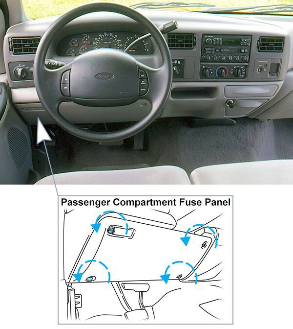
Passenger Compartment Fuse Panel:
The fuse panel is located below and to the left of the steering wheel by the brake pedal. Remove the panel cover to access the fuses. To remove the fuse panel cover, turn the panel fasteners counterclockwise.
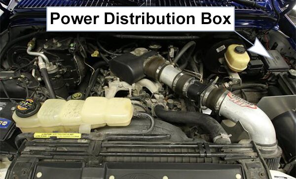
Power Distribution Box:
The power distribution box, trailer tow and electronic shift on the fly relay blocks are located in the engine compartment near the brake master cylinder. The power distribution box contains high-current fuses that protect your vehicle’s main electrical systems from overloads.
Fuse Box Diagrams
1998
Passenger Compartment Fuse Panel
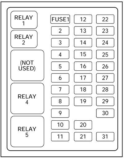
List of fuses in the passenger compartment fuse panel (1998)
| № | A | Description |
|---|---|---|
| 1 | 15A | Flasher Relay |
| 2 | 5A | Instrument Cluster |
| 3 | 25A | Cigar Lighter |
| 4 | 5A | Park Lamp Relay, Headlamp Relay, Autolamp Module Remote Anti-Theft Personality (RAP) Module, Power Mirror Switch |
| 5 | 15A | Digital Transmission Range (DTR) Sensor (A/T), Backup Lamp Switch (M/T), Daytime Running Lights (DRL) Module, Speed Control Servo/Amplifier Assembly, Heater-A/C Control Assembly, Blend Door Actuator |
| 6 | 5A | Shift Lock Actuator, Generic Electronic Module (GEM), Rear Air Suspension (RAS) Module |
| 7 | – | Not Used |
| 8 | 5A | Radio, Main Light Switch, Remote Anti – Theft Personality (RAP) Module |
| 9 | – | Not Used |
| 10 | – | Not Used |
| 11 | 30A | Washer Pump Relay, Wiper Run/Park Relay, Wiper Hi/LO Relay, Windshield Wiper Motor |
| 12 | 5A | Data Link Connector (DLC) |
| 13 | 15A | Rear Anti-Lock Brake System (RABS) Module, Brake On/Off (BOO) Switch, Brake Pressure Switch |
| 14 | 15A | Battery Saver Relay, Interior Lamp Relay |
| 15 | 5A | Generic Electronic Module (GEM) |
| 16 | 20A | Instrument Cluster (W/O DRL), Daytime Running Lamps (DRL) Module, Hi-Beam Headlamps (Power supplied through Multi-Function Switch) |
| 17 | – | Not Used |
| 18 | 5A | Park Lamp Relay, Trailer Electronic Brake Controller, Main Light Switch, Trailer Tow Run Relay, Front Park/Turn Lamps, License Lamps, Stop/Park/Turn Lamps, Tail/Side Marker Lamps (Power supplied through Main Light Switch) |
| 19 | 10A | Instrument Cluster, Air Bag Diagnostic Monitor |
| 20 | 5A | Powertrain Control Module (PCM), Generic Electronic Module (GEM)/Central Timer Module (CTM) |
| 21 | 15A | Clutch Pedal Position (CPP) Switch (W/O RAP), Starter Interrupt Relay (W/RAP) |
| 22 | 10A | Air Bag Diagnostic Monitor, Passive De – Activation (PAD) Module |
| 23 | 10A | Trailer tow Battery Charge Relay, 4X4 Hub Solenoid, 4X2 Hub Solenoid, Flasher Relay, Shift on the Fly Relay |
| 24 | 10A | Blower Relay |
| 25 | 5A | 4 Wheel Anti – Lock Brake System (4WABS) Module, 4WABS Relay |
| 26 | 10A | Daytime Running Lamps (DRL) Module, Right Headlamp |
| 27 | 5A | Main Light Switch, Fog Lamp Relay |
| 28 | 10A | Left Headlamp |
| 29 | 5A | Autolamp Module, Instrument Cluster, Transmission Control Switch (TCS), Brake Warning Resistor/Diode Assembly (W/RABS) |
| 30 | 30A | Radio Noise Capacitor, Ignition Coil, PCM Power Diode |
| 31 | – | Not Used |
| Relay 1 | – | Interior Lamp Relay |
| Relay 2 | – | Battery Saver Relay |
| Not Used | – | Not Used |
| Relay 4 | – | One Touch Down Relay |
| Relay 5 | – | ACC Delay Relay |
Power Distribution Box
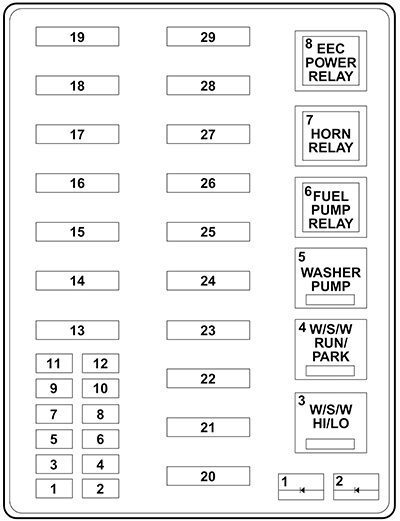
List of fuses in the power distribution box (1998)
| № | A | Description |
|---|---|---|
| 1 | 20A* | Trailer Tow Running Lamp Relay, Trailer Tow Backup Lamp Relay |
| 2 | 10A* | Air Bag Diagnostic Monitor |
| 3 | 15A* | All Unlock Relay, All Lock Relay, Driver Unlock Relay, LH Power Door Lock Switch, RH Power Door Lock Switch |
| 4 | 15A* | Rear Air Suspension (RAS) |
| 5 | 20A* | Horn Relay |
| 6 | 15A* | Radio, Premium Sound Amplifier, CD Changer |
| 7 | 15A* | Main Light Switch, Park Lamp Relay |
| 8 | 30A* | Main Light Switch, Headlamp Relay, Multi-Function Switch |
| 9 | 15A* | Daytime Running Lamps (DRL) Module, Fog Lamp Relay |
| 10 | 25A* | Auxiliary Power Socket |
| 11 | – | Not Used |
| 12 | – | Not Used |
| 13 | – | Not Used |
| 14 | 60A**/20A** | 4 Wheel Anti-Lock Brake System (4WABS) Module/Ignition Switch (W/RABS Only) |
| 15 | 50A** | Rear Air Suspension Compressor |
| 16 | 40A** | Trailer Tow Battery Charge Relay, Engine Fuse Module (Fuse 2) |
| 17 | 30A** | Shift on the Fly Relay, Transfer Case Shift Relay |
| 18 | 30A** | Power Seat Control Switch |
| 19 | 20A** | Fuel Pump Relay |
| 20 | 50A** | Ignition Switch |
| 21 | 50A** | Ignition Switch |
| 22 | 50A** | Junction Box Fuse/Relay Panel Battery Feed |
| 23 | 40A** | Blower Relay |
| 24 | 30A** | PCM Power Relay, Engine Fuse Module (Fuse 1) |
| 25 | 30A** | Junction Box Fuse/Relay Panel, ACC Delay Relay |
| 26 | – | Not Used |
| 27 | – | Not Used |
| 28 | 30A** | Trailer Electronic Brake Controller |
| 29 | – | Not Used |
| * Mini fuses ** Maxi fuses | ||
1999
Passenger Compartment Fuse Panel
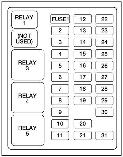
List of fuses in the passenger compartment fuse panel (1999)
| № | A | Description |
|---|---|---|
| 1 | 20A | Electronic Flasher |
| 2 | 5A | Instrument Cluster, Powertrain Control Module (PCM) Keep Alive Memory |
| 3 | 20A | Cigar Lighter, OBDII |
| 4 | 10A | Glove Box Lamp, Map Lamps, Power Mirrors, Underhood Lamp |
| 5 | – | Not Used |
| 6 | – | Not Used |
| 7 | 5A | Power Window Lock Switch Illumination |
| 8 | 5A | Radio, Headlamp Switch Illumination |
| 9 | – | Not Used |
| 10 | – | Not Used |
| 11 | 10A | Washer Pump, Wiper Run/Park Relay Coil, Wiper Hi/LO Relay Coil, Washer Pump Relay Coil |
| 12 | 15A | Horn |
| 13 | 20A | Stop Lamps, Center High – mount Stop Lamp, Trailer Tow Stop Lamp |
| 14 | 10A | Dome Lamp, Cargo Lamp, Courtesy Lamps |
| 15 | 5A | Generic Electronic Module (GEM), Powertrain Control Module (PCM), Anti – lock Brake System (ABS) Module, Brake Shift Interlock, Speed Control |
| 16 | 15A | Instrument Cluster, Hi – beam Headlamps |
| 17 | – | Not Used |
| 18 | – | Not Used |
| 19 | 10A | Auxiliary Powertrain Control Module (APCM) (Diesel only), Instrument Cluster, GEM Module, Overdrive Cancel Switch, Idle Validation Switch (Diesel only), Overhead Console |
| 20 | 15A | Starter Motor Relay Coil, PCM (Gasoline only) |
| 21 | – | Not Used |
| 22 | 10A | Air Bag Module, Passenger Air Bag Activation Switch, Blower Motor Relay Coil |
| 23 | 10A | Electronic Flasher |
| 24 | 10A | Blend Door Actuator, Trailer Tow Battery Charge Relay Coil |
| 25 | 5A | 4-Wheel Anti – Lock Brake System (4WABS) Module |
| 26 | – | Not Used |
| 27 | 10A | Ignition Run Power Feed (Customer Access) |
| 28 | 10A | Brake Shift Interlock, DRL Relay Coil, Speed Control Module, Backup Lamps, Trailer Tow Backup Lamp Relay Coil, Electronic Shift On The Fly Hub Lock Solenoid |
| 29 | 5A | Instrument Cluster (Charge and Airbag Warning Lamps) |
| 30 | 30A | PCM Relay Coil, Ignition Coil (Gasoline only), Fuel Heater (Diesel only), Wastegate Solenoid (Diesel only), Injector Driver Module Relay Coil (Diesel only) |
| 31 | – | Not Used |
| Relay 1 | – | Interior Lamp Relay |
| Relay 2 | – | Not Used |
| Relay 3 | – | Horn |
| Relay 4 | – | Power Window One Touch Down Relay |
| Relay 5 | – | Accessory Delay Relay |
Power Distribution Box
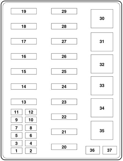
List of fuses in the power distribution box (1999)
| № | A | Description |
|---|---|---|
| 1 | 7.5A* | Trailer Tow Left Stop/Turn Lamp |
| 2 | 10A* | Air Bag Module |
| 3 | 7.5A* | Trailer Tow Right Stop/Turn Lamp |
| 4 | 20A* | Trailer Tow Backup Lamps, Trailer Tow Park Lamps |
| 5 | 20A* (Gasoline only) 5A* (Diesel only) | Gasoline only – PCM, Two Speed Fuel Pump Relay Coil, Fuel Pump Relay Coil, Mass Air Flow Sensor, Fuel Injectors. Diesel only – Dual Alternator “A” Field. |
| 6 | 10A* (Diesel only) | Gasoline only – Not Used. Diesel only – Single or Dual Alternator “A” Field, Regulator. |
| 7 | 20A* (Gasoline only) 5A* (Diesel only) | Gasoline only – Vapor Managment Valve, HEGO Sensors, Intake Manifold Communication Control, EVR Solenoid, PCM, Canister Vent Solenoid. Diesel only – Dual Alternator “A” Field. |
| 8 | 15A* | Trailer Tow Electronic Brake Illumination, Park Lamps, Trailer Tow Park Lamp Relay Coil |
| 9 | 10A* | Left Headlamp |
| 10 | 25A* | Power Point |
| 11 | 10A* | Right Headlamp (Low Beam) |
| 12 | 10A* | Daytime Running Lamps (DRL) Resistor |
| 13 | 30A** | Multi-function Switch, Headlamps |
| 14 | 60A** | Anti-Lock Brake System |
| 15 | 30A** | Windshield Wiper Motor |
| 16 | 30A** | Trailer Tow Battery Charge |
| 17 | 30A** | Electronic Shift On The Fly Relay, Transfer Case Shift Motor |
| 18 | 30A** | Power Seat |
| 19 | 20A** | Fuel Pump Motor, PCM |
| 20 | 50A** | Ignition Switch (B4 & B5) |
| 21 | 50A** | Ignition Switch (B1 & B3) |
| 22 | 50A** | Instmment Panei Junction Box |
| 23 | 40A** | Blower Motor |
| 24 | 30A** | Power Distribution Box |
| 25 | 30A*** | Power Windows |
| 26 | 20A** | If equipped with Remote Keyless Entry – Driver Door Unlock Relay Coil, All Door Unlock Relay Coil, All Door Lock Relay Coil, Park Lamp Flash Relay. If not equipped with Remote Keyless Entry – Power Door Lock Motors. |
| 27 | 30A* (Diesel only) | Gasoline only – Not Used Diesel only – Injector Driver Module |
| 28 | 30A** | Trailer Tow Electronic Brake Controller |
| 29 | 20A** | Radio |
| 30 | – | PCM Power Relay |
| 31 | – | Blower Motor Relay |
| 32 | – | Two Speed Fuel Pump Relay (Gasoline only), Injector Driver Module Power Relay (Diesel only) |
| 33 | – | Washer Pump Relay |
| 34 | – | Windshield Wiper Park/Run Relay |
| 35 | – | Windshield Wiper HI/LO Relay |
| 36 | – | Not Used |
| 37 | – | PCM Relay Diode |
| 38 | – | Trailer Tow Backup Lamp Relay |
| 39 | – | Trailer Tow Battery Charge Relay |
| 40 | – | Electronic Shift On The Fly Relay #1, Electronic Shift On The Fly Relay #2 |
| * Mini Fuses ** Maxi Fuses *** Circuit Breaker | ||
Conclusion
Because the 1998–1999 Ford F-250, F-350, F-450, and F-550 span two distinct body styles and electrical designs, knowing which generation your truck belongs to is the first step in locating its fuse box and relays correctly. The 1998 model follows the simpler, older relay-based layout, while the 1999 Super Duty introduces a more centralized fuse box system closer to modern trucks.
Whichever year you own, always handle fuses and relays carefully, confirm amperage ratings before replacing components, and use a wiring diagram when relay locations aren’t immediately obvious. If electrical problems persist after checking your fuses and relays, consulting a mechanic experienced with this transitional Ford Super Duty generation is a wise next step.