Learn about Ford Five Hundred (2005-2007) fuse box and relay’s locations, functions, and maintenance tips for optimal vehicle electrical system.
The Ford Five Hundred was a full-size sedan produced from 2005 to 2007, offering a spacious interior and a range of modern conveniences for its time. Like all vehicles, it relies on a network of fuses and relays to protect its electrical system from overloads, short circuits, and wiring damage. These small components play a big role in keeping everything from the headlights to the power seats functioning properly.
If you’re experiencing issues like a dead radio, non-working power windows, or a malfunctioning interior light, a blown fuse or faulty relay is often the culprit. Knowing exactly where to find your Five Hundred’s fuse boxes and how to safely access them, can help you resolve many electrical issues yourself without an unnecessary trip to the shop.
This guide covers the fuse box and relay locations for the 2005–2007 Ford Five Hundred, along with safe access methods and tips for identifying the correct fuse or relay using your vehicle’s diagrams.
MUST READ: DYI – How to Check Car Fuses?
(2005-2007) Ford Five Hundred fuse box and relay with Diagram
WARNING
- Never replace a fuse with one that has a higher amperage rating.
- A fuse with a too-high amperage could damage the electrical part and cause a fire.
- On no account should fuses be repaired (e.g. patched up with tin foil or wire) as this may cause serious damage elsewhere in the electrical circuit or cause a fire.
- If a fuse blows repeatedly, do not keep replacing it. Instead, have the cause for the repeated short circuit or overload tracked and fixed.
- Terminal and harness assignments for individual connectors will vary depending on vehicle equipment level, model, and market.
Ford Five Hundred (2005-2007) fuse assignment
Ford Five Hundred Year of production: 2005, 2006, 2007
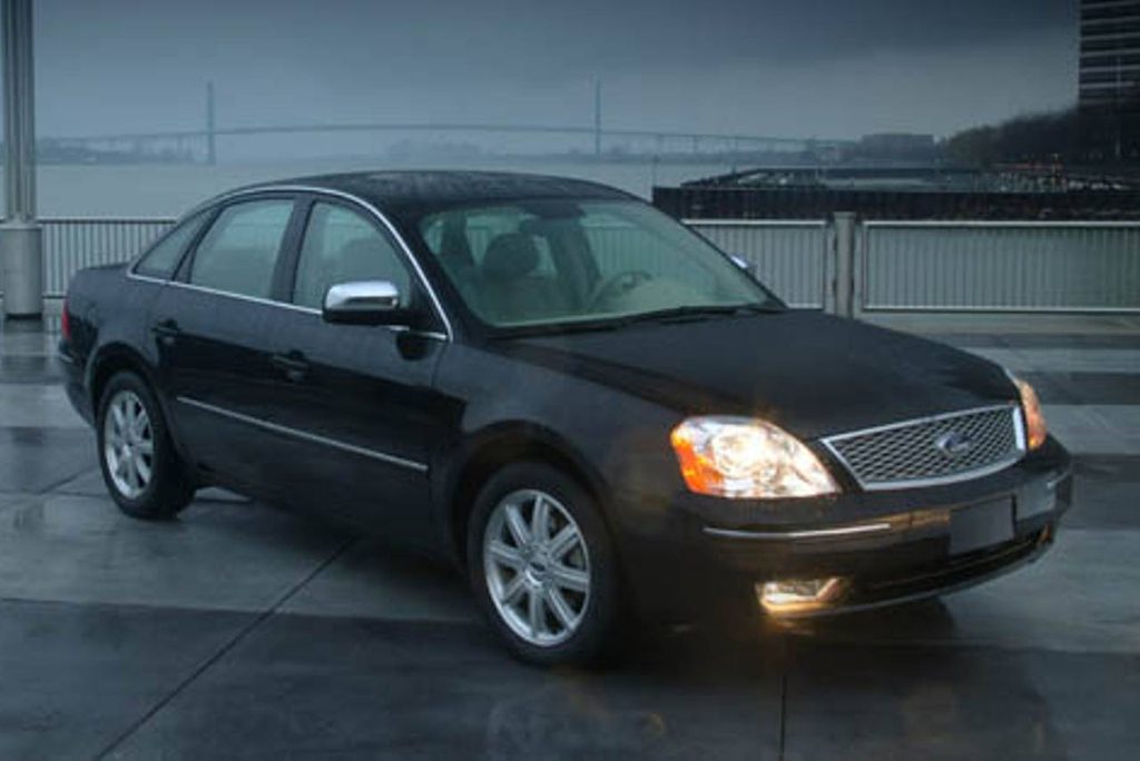
Where Are the Fuse Boxes Located on the Ford Five Hundred?
The 2005–2007 Ford Five Hundred is equipped with two main fuse box locations: one in the engine compartment and one inside the cabin. This two-box layout is standard for this generation and makes troubleshooting relatively straightforward once you know where to look.
1. Engine Compartment Fuse Box (Power Distribution Box)
The primary fuse box is located in the engine bay, mounted near the battery on the driver’s side, close to the firewall.
How to access it:
- Open the hood and locate the black plastic cover near the battery.
- Unclip or unscrew the retaining tabs holding the cover in place, depending on your specific trim.
- Lift the cover straight up to reveal the fuses and relays inside.
This fuse box protects high-amperage components such as the headlights, engine cooling fan, horn, and starter relay. Because this area is exposed to engine heat and moisture, make sure the cover is fully sealed after inspection to prevent corrosion.
2. Interior Fuse Panel (Instrument Panel Fuse Box)
The cabin fuse box is located inside the vehicle, typically under the dashboard on the driver’s side, near the left kick panel.
How to access it:
- Sit in the driver’s seat and locate the small panel cover to the left of the steering column, near the door.
- Gently pull or unclip the cover, it’s usually secured with simple plastic retaining clips.
- Once removed, you’ll see the fuse layout along with a few compact relays.
This panel controls interior circuits such as the radio, power windows, power seats, dashboard lights, wipers, and central locking system. This is the fuse box you’ll likely need to check most often for everyday electrical issues.
3. Trunk-Mounted Auxiliary Relays (If Equipped)
Some Five Hundred trims, particularly those equipped with advanced features like the power liftgate or upgraded audio systems, may include a small auxiliary relay panel located in the trunk area, often near the trunk latch mechanism or along the interior trunk wall.
How to access it:
- Open the trunk and check along the side panels or near the trunk latch for a small access panel or exposed relay bracket.
- Not all trims include this additional panel, check your owner’s manual to confirm whether your specific configuration has one.
How to Identify the Right Fuse or Relay
Both the engine bay and interior fuse boxes include a printed diagram, usually located on the inside of the fuse box cover, listing each fuse and relay by number, amperage rating, and function.
When troubleshooting:
- Identify the malfunctioning component (e.g., “power seat” or “radio”) and match it to its corresponding number on the diagram.
- Confirm the amperage rating on the old fuse matches the replacement before installing a new one.
- For relays, use the diagram to confirm the correct slot, since several relays in the box may look identical despite controlling different systems.
If the printed diagram is missing or difficult to read, refer to your owner’s manual for a detailed fuse box diagram specific to your Five Hundred’s trim level, as configurations can vary slightly between base models and higher trims with additional electrical features like all-wheel drive or premium audio.
Safety Precautions Before Checking Fuses or Relays
- Turn off the ignition and remove the key before touching any fuse or relay.
- For more involved electrical work, disconnect the negative battery terminal to prevent accidental short circuits.
- Use the fuse puller tool, often built into the fuse box cover, rather than metal tools like screwdrivers, which can cause sparking.
- Never replace a fuse with one of a higher amperage rating than specified, as this can overload the circuit and create a fire hazard.
- If a replacement fuse blows immediately, stop and inspect the circuit for an underlying short rather than continuing to swap fuses.
Checking and Replacing Fuses in Ford Five Hundred
If electrical components in the vehicle are not working, a fuse may have blown. Blown fuses are identified by a broken wire within the fuse. Check the appropriate fuses before replacing any electrical components.
Location of Fuse Boxes
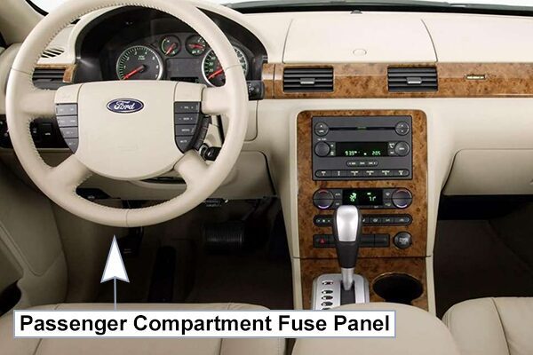
Passenger Compartment Fuse Panel/Smart Junction Box (SJB):
The fuse panel is located under the instrument panel to the left of the steering wheel.
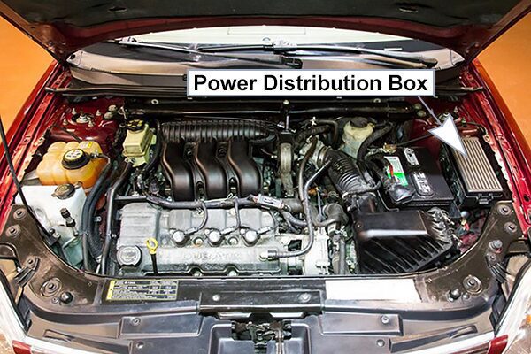
Power Distribution Box:
The power distribution box is located in the engine compartment. The power distribution box contains high-current fuses that protect your vehicle’s main electrical systems from overloads.
Fuse Box Diagrams
2005
Passenger Compartment Fuse Panel/Smart Junction Box (SJB)
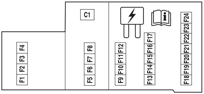
List of fuses in the passenger compartment fuse panel/smart junction box (sjb) (2005)
| № | A | Description |
|---|---|---|
| F1 | 20A | High beams |
| F2 | 15A | Interior lamps (Courtesy and demand lamps), Delayed accessory (Power Windows and moonroof) |
| F3 | 25A | Access/Security (Power door lock actuators, Decklid lock actuator, Decklid solenoid) |
| F4 | 15A | Adjustable pedal switch |
| F5 | 20A | Horns |
| F6 | 20A | Audio (Subwoofer) |
| F7 | 7.5A | Power/Keep Alive Memory (KAM): Cluster and Powertrain Control Module (PCM), Climate control, Analog clock |
| F8 | 15A | Park lamps, Side markers, Trailer tow protect |
| F9 | 20A | Cigar lighter, Data Link Connector (DLC) |
| F10 | 7.5A | Mirrors and memory module |
| F11 | 20A | Audio, Family Entertainment System (FES) |
| F12 | 10A | Back-up lamps, Electrochromatic mirror, Reverse Sensing System (RSS), Trailer tow protect |
| F13 | 7.5A | Audio |
| F14 | 7.5A | Starter relay coil, PCM |
| F15 | 10A | Delayed accessory (Driver window motor logic, Moonroof, Audio, Driver door lock switch illumination) |
| F16 | 10A | Rear defroster indicator, Heated mirrors |
| F17 | 30A | Rear defroster |
| F18 | 10A | PCM relay coil, Shifter Brake-Shift Interlock (BSI), Passive Anti-Theft System (PATS) module, Fuel relay coil, Brake lamps, Center High-Mounted Stop Lamp (CHMSL) |
| F19 | 10A | Anti-lock Brake System (ABS)/Traction control module, All Wheel Drive (AWD) module, RSS, Heated seat modules |
| F20 | 7.5A | Cluster, Climate control |
| F21 | 7.5A | Restraint Control Module (RCM) |
| F22 | 7.5A | Electrochromatic mirror, Compass module |
| F23 | 7.5A | Wiper relay coü, Blower relay coü, Cluster logic |
| F24 | 7.5A | Occupant Classification Sensor (OCS), Passenger Air bag Deactivation (PAD) |
| C1 | 30A Circuit breaker | Delayed accessory (Front passenger window, Rear passenger Windows (via window switch), Window switch illumination, Backlighting |
Power Distribution Box
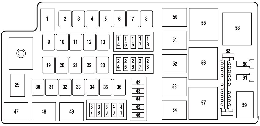
List of fuses in the power distribution box (2005)
| № | A | Description |
|---|---|---|
| 1 | 80A* | SJB, SJB fuses 1, 2, 3, 4, 5, 8 and 12 |
| 2 | – | Not used |
| 3 | – | Not used |
| 4 | 50A* | Wiper RUN/ACC relay to PDB, PDB fuses 37 and 38 |
| 5 | – | Not used |
| 6 | 20A* | Moonroof |
| 7 | – | Not used |
| 8 | 60A* | Engine cooling fan |
| 9 | – | Not used |
| 10 | 40A* | Anti-lock Brake System (ABS) (Motor) |
| 11 | 30A* | Starter |
| 12 | 30A* | Powertrain Control Module (PCM) relay |
| 13 | 20A* | ABS (Valves) |
| 14 | – | Not used |
| 15 | – | Not used |
| 16 | 15A** | Traction Control Module (TCM) |
| 17 | 20A** | Power point (Console) |
| 18 | 10A** | Altemator |
| 19 | 40A* | Logic feed to SJB, SJB solid State devices |
| 20 | – | Not used |
| 21 | 40A* | Rear defroster |
| 22 | 30A* | Power seat motors (passenger) |
| 23 | 30A* | Heated seat modules |
| 24 | 15A** | Fog lamps |
| 25 | 10A** | A/C clutch relay, A/C compressor clutch |
| 26 | – | Not used |
| 27 | – | Not used |
| 28 | 15A** | Fuel relay (Fuel pump driver module, Fuel pump) |
| 29 | 80A* | SJB power, SJB (Circuit breaker, Fuses 6, 7, 9, 10, 11 and 15) |
| 30 | 30A* | Driver window motor |
| 31 | – | Not used |
| 32 | – | Not used |
| 33 | 30A* | Driver seat motors, Memory module |
| 34 | 30A* | Ignition switch (to SJB) |
| 35 | – | Not used |
| 36 | 40A* | Front A/C blower motor |
| 37 | 30A** | Front wiper, Front washer |
| 38 | 5A** | Heated Positive Crankcase Ventilation (PCV) valve |
| 39 | – | Not used |
| 40 | 10A** | TCM, EVMV, Canister vent, ESM, Exhaust Gas Oxygen heaters, A/C clutch |
| 41 | 15A** | PCM, Injectors, Ignition coils, Mass Air Flow (MAF) sensor |
| 42 | – | Not used |
| 43 | – | Not used |
| 44 | – | Not used |
| 45 | – | Not used |
| 46 | – | Not used |
| 47 | – | Not used |
| 48 | 1⁄2 ISO relay | Fog lamps |
| 49 | – | Not used |
| 50 | – | Not used |
| 51 | 1⁄2 ISO relay | A/C clutch |
| 52 | – | Not used |
| 53 | 1⁄2 ISO relay | Fuel pump driver module, Fuel pump |
| 54 | – | Not used |
| 55 | Full ISO relay | PCM relay, PDB fuses 40 and 41 |
| 56 | Full ISO relay | Starter motor solenoid |
| 57 | Full ISO relay | Front A/C blower motor |
| 58 | High current relay | Wipers |
| 59 | – | Not used |
| 60 | 1A Diode | PCM |
| 61 | 1A Diode | PCM |
| * Cartridge Fuses ** Mini Fuses | ||
2006
Passenger Compartment Fuse Panel/Smart Junction Box (SJB)
List of fuses in the passenger compartment fuse panel/smart junction box (sjb) (2006)
| № | A | Description |
|---|---|---|
| F1 | 20A | High beams |
| F2 | 15A | Interior lamps (Courtesy and demand lamps), Delayed accessory (Power Windows and moonroof) |
| F3 | 25A | Access/Security (Power door lock actuators, Decklid lock actuator, Decklid solenoid) |
| F4 | 15A | Adjustable pedal switch |
| F5 | 20A | Horns |
| F6 | 20A | Audio (Subwoofer) |
| F7 | 7.5A | Power/Keep Alive Memory (KAM): Cluster and Powertrain Control Module (PCM), Climate control, Analog clock |
| F8 | 15A | Park lamps, Side markers, Trailer tow protect |
| F9 | 20A | Cigar lighter, Data Link Connector (DLC) |
| F10 | 7.5A | Mirrors and memory module |
| F11 | 20A | Audio, Family Entertainment System (FES) |
| F12 | 10A | Back-up lamps, Electrochromatic mirror, Reverse Sensing System (RSS), Trailer tow protect |
| F13 | 7.5A | Audio |
| F14 | 7.5A | Starter relay coil, PCM |
| F15 | 10A | Delayed accessory (Driver window motor logic, Moonroof, Audio, Driver door lock switch illumination) |
| F16 | 10A | Rear defroster indicator, Heated mirrors |
| F17 | 30A | Rear defroster |
| F18 | 10A | PCM relay coil, Shifter Brake-Shift Interlock (BSI), Passive Anti-Theft System (PATS) module, Fuel relay coil, Brake lamps, Center High-Mounted Stop Lamp (CHMSL) |
| F19 | 10A | Anti-lock Brake System (ABS)/Traction control module, All Wheel Drive (AWD) module, RSS, Heated seat modules |
| F20 | 7.5A | Cluster, Climate control |
| F21 | 7.5A | Restraint Control Module (RCM) |
| F22 | 7.5A | Electrochromatic mirror, Compass module |
| F23 | 7.5A | Wiper relay coil, Blower relay coil, Cluster logic |
| F24 | 7.5A | Occupant Classification Sensor (OCS), Passenger Air bag Deactivation (PAD) |
| C1 | 30A Circuit breaker | Delayed accessory (Front passenger window, Rear passenger Windows (via wundow switch), Window switch illumination, Backlighting |
Power Distribution Box
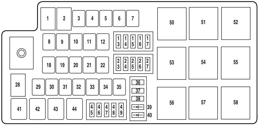
List of fuses in the power distribution box (2006)
| № | A | Description |
|---|---|---|
| 1 | 80A* | SJB, SJB fuses 1, 2, 3, 4, 5, 8 and 12 |
| 2 | – | Not used |
| 3 | 30A* | Front wiper, Front washer |
| 4 | – | Not used |
| 5 | 20A* | Moonroof |
| 6 | – | Not used |
| 7 | 60A* | Engine cooling fan |
| 8 | – | Not used |
| 9 | 40A* | Anti-lock Brake System (ABS) (Motor) |
| 10 | 30A* | Starter |
| 11 | 30A* | Powertrain Control Module (PCM) relay |
| 12 | 20A* | ABS (Valves) |
| 13 | – | Not used |
| 14 | Not used | |
| 15 | 15A** | Traction Control Module (TCM) |
| 16 | 20A** | Power point (Console) |
| 17 | 10A** | Alternator |
| 18 | 40A* | Logic feed to SJB, SJB solid State devices |
| 19 | – | Not used |
| 20 | 40A* | Rear defroster |
| 21 | 30A* | Power seat motors (passenger) |
| 22 | 30A* | Heated seat modules |
| 23 | 15A** | Fog lamps |
| 24 | 10A** | A/C clutch relay, A/C compressor clutch |
| 25 | – | Not used |
| 26 | – | Not used |
| 27 | 15A** | Fuel relay (Fuel pump driver module, Fuel pump) |
| 28 | 80A* | SJB power, SJB (Circuit breaker, Fuses 6, 7, 9, 10, 11 and 15) |
| 29 | 30A* | Driver window motor |
| 30 | – | Not used |
| 31 | – | Not used |
| 32 | 30A* | Driver seat motors, Memory module |
| 33 | 30A* | Ignition switch (to SJB) |
| 34 | – | Not used |
| 35 | 40A* | Front A/C blower motor |
| 36 | – | Not used |
| 37 | – | Not used |
| 38 | – | Not used |
| 39 | 1A Diode | PCM |
| 40 | 1A Diode | A/C clutch |
| 41 | 1⁄2 ISO relay | Fog lamps |
| 42 | – | Not used |
| 43 | 1⁄2 ISO relay | A/C clutch |
| 44 | 1⁄2 ISO relay | Fuel pump driver module, Fuel pump |
| 45 | – | Not used |
| 46 | 5A** | Heated Positive Crankcase Ventilation (PCV) valve |
| 47 | – | Not used |
| 48 | 10A** | TCM, EVMV, Canister vent, ESM, Exhaust Gas Oxygen heaters, A/C clutch |
| 49 | 15A** | PCM, Injectors, Ignition coils, Mass Air Flow (MAF) sensor |
| 50 | Full ISO relay | PCM relay, PDB fuses 40 and 41 |
| 51 | Full ISO relay | Starter motor solenoid |
| 52 | Full ISO relay | Front A/C blower motor |
| 53 | – | Not used |
| 54 | – | Not used |
| 55 | – | Not used |
| 56 | – | Not used |
| 57 | Full ISO relay | Front wipers |
| 58 | – | Not used |
| * Cartridge Fuses ** Mini Fuses | ||
2007
Passenger Compartment Fuse Panel/Smart Junction Box (SJB)
List of fuses in the passenger compartment fuse panel/smart junction box (sjb) (2007)
| № | A | Description |
|---|---|---|
| F1 | 20A | High beams |
| F2 | 15A | Interior lamps (Courtesy and demand lamps), Delayed accessory (Power Windows and moonroof) |
| F3 | 25A | Access/Security (Power door lock actuators, Decklid lock actuator, Decklid solenoid) |
| F4 | 15A | Adjustable pedal switch |
| F5 | 20A | Horns |
| F6 | 20A | Audio (Subwoofer) |
| F7 | 7.5A | Power/Keep Alive Memory (KAM): Cluster and Powertrain Control Module (PCM), Climate control, Analog clock |
| F8 | 15A | Park lamps, Side markers, Trailer tow protect |
| F9 | 20A | Cigar lighter, Data Link Connector (DLC) |
| F10 | 7.5A | Mirrors and memory module, SDARS |
| F11 | 20A | Audio, Family Entertainment System (FES) |
| F12 | 10A | Back-up lamps, Electrochromatic mirror, Reverse Sensing System (RSS), Trailer tow protect |
| F13 | 7.5A | Audio |
| F14 | 7.5A | Starter relay coil, PCM |
| F15 | 10A | Delayed accessory (Driver window motor logic, Moonroof, Audio, Driver door lock switch illumination) |
| F16 | 10A | Rear defroster indicator, Heated mirrors |
| F17 | 30A | Rear defroster |
| F18 | 10A | PCM relay coil, Shifter Brake-Shift Interlock (BSI), Passive Anti-Theft System (PATS) module, Fuel relay coil, Brake lamps, Center High-Mounted Stop Lamp (CHMSL) |
| F19 | 10A | Anti-lock Brake System (ABS)/Traction control module, All Wheel Drive (AWD) module, RSS, Heated seat modules |
| F20 | 7.5A | Cluster, Climate control |
| F21 | 7.5A | Restraint Control Module (RCM) |
| F22 | 7.5A | Electrochromatic mirror, Compass module |
| F23 | 7.5A | Wiper relay coil, Blower relay coil, Cluster logic |
| F24 | 7.5A | Occupant Classification Sensor (OCS), Passenger Air bag Deactivation (PAD) |
| C1 | 30A Circuit breaker | Delayed accessory (Front passenger window, Rear passenger Windows (via window switch), Window switch illumination, Backlighting |
Power Distribution Box
List of fuses in the power distribution box (2007)
| № | A | Description |
|---|---|---|
| 1 | 80A* | SJB, SJB fuses 1, 2, 3, 4, 5, 8 and 12 |
| 2 | – | Not used |
| 3 | 30A* | Front wiper, Front washer |
| 4 | – | Not used |
| 5 | 20A* | Moonroof |
| 6 | – | Not used |
| 7 | 60A* | Engine cooling fan |
| 8 | – | Not used |
| 9 | 40A* | Anti-lock Brake System (ABS) (Motor) |
| 10 | 30A* | Starter |
| 11 | 30A* | Powertrain Control Module (PCM) relay |
| 12 | 20A* | ABS (Valves) |
| 13 | – | Not used |
| 14 | – | Not used |
| 15 | 15A** | Traction Control Module (TCM) |
| 16 | 20A** | Power point (Console) |
| 17 | 10A** | Alternator |
| 18 | 40A* | Logic feed to SJB, SJB solid State devices |
| 19 | – | Not used |
| 20 | 40A* | Rear defroster |
| 21 | 30A* | Power seat motors (passenger) |
| 22 | 30A* | Heated seat module |
| 23 | 15A** | Fog lamps |
| 24 | 10A** | A/C clutch relay, A/C compressor clutch |
| 25 | – | Not used |
| 26 | – | Not used |
| 27 | 15A** | Fuel relay (Fuel pump driver module, Fuel pump) |
| 28 | 80A* | SJB power, SJB (Circuit breaker, Fuses 6, 7, 9, 10, 11 and 15) |
| 29 | 30A* | Driver window motor |
| 30 | – | Not used |
| 31 | – | Not used |
| 32 | 30A* | Driver seat motors, Memory module |
| 33 | 30A* | Ignition switch (to SJB) |
| 34 | – | Not used |
| 35 | 40A* | Front A/C blower motor |
| 36 | – | Not used |
| 37 | – | Not used |
| 38 | – | Not used |
| 39 | 1A Diode | PCM |
| 40 | 1A Diode | A/C clutch |
| 41 | 1⁄2 ISO relay | Fog lamps |
| 42 | – | Not used |
| 43 | 1⁄2 ISO relay | A/C clutch |
| 44 | 1⁄2 ISO relay | Fuel pump driver module, Fuel pump |
| 45 | – | Not used |
| 46 | 5A** | Heated Positive Crankcase Ventilation (PCV) valve |
| 47 | – | Not used |
| 48 | 10A** | TCM, EVMV, Canister vent, ESM, Exhaust Gas Oxygen heaters, A/C clutch |
| 49 | 15A** | PCM, Injectors, Ignition coils, Mass Air Flow (MAF) sensor |
| 50 | Full ISO relay | PCM relay, PDB fuses 40 and 41 |
| 51 | Full ISO relay | Starter motor solenoid |
| 52 | Full ISO relay | Front A/C blower motor |
| 53 | – | Not used |
| 54 | – | Not used |
| 55 | – | Not used |
| 56 | – | Not used |
| 57 | Full ISO relay | Front wipers |
| 58 | – | Not used |
| * Cartridge Fuses ** Mini Fuses | ||
Conclusion
Knowing the fuse box and relay locations on your 2005–2007 Ford Five Hundred makes it much easier to handle minor electrical issues without unnecessary guesswork. With two main fuse box locations; one under the hood and one inside the cabin, plus a possible auxiliary panel in the trunk for certain trims, this sedan is relatively simple to troubleshoot once you’re familiar with its layout.
Always handle fuses and relays with care, confirm amperage ratings before replacing any component, and use the printed diagram to correctly identify each fuse or relay. If an electrical issue persists after replacing a fuse, or if you’re unsure about diagnosing the problem yourself, consulting a qualified mechanic or Ford dealership technician is the safest way to avoid further electrical complications.