The fuse boxes in the Toyota Yaris Hatchback (XP90; 2006–2008) protect the vehicle’s electrical circuits from overloads and short circuits. Each fuse is designed to fail before wiring or electrical components are damaged. Relays work as electrically controlled switches, allowing systems such as the headlights, cooling fan, fuel pump, and horn to operate safely.
Knowing the correct fuse box location makes troubleshooting much easier. If the interior lights, power windows, radio, headlights, or another electrical system stops working, checking the appropriate fuse or relay is often a useful first step. The Yaris XP90 mainly uses one fuse and relay area in the engine compartment and another fuse area under the dashboard.
Safety Precautions Before Checking Fuses
Always switch off the ignition and electrical accessories before inspecting or replacing a fuse. For more involved electrical work, disconnect the negative battery terminal, but remember that doing so may erase clock, radio, or vehicle-system settings.
Use only a replacement fuse with the same amperage rating as the original. The rating is normally printed on the fuse and shown in the fuse diagram. Installing a fuse with a higher rating can overheat the wiring and create a fire risk. Installing a lower-rated fuse may cause it to fail repeatedly.
Never replace a fuse with wire, foil, or another metal object. If the replacement fuse blows immediately, or if the same fuse fails repeatedly, there is likely an underlying short circuit or electrical fault. Stop replacing fuses and have the vehicle inspected.
Take extra care around wiring near the steering column, airbag components, and engine-control equipment. If battery disconnection or testing is required near an airbag system, professional assistance is recommended.
Using the Fuse and Relay Diagram
The fuse diagram identifies each fuse by its position, circuit, and amperage. Start by identifying the electrical feature that is not working, then find its corresponding fuse in the relevant diagram. Remember that one fuse may supply several related components, so a fault may affect more than one function.
The relay diagram identifies relays by position and purpose. Because relay layouts can differ between engines and markets, use the diagram specific to the Toyota Yaris Hatchback (XP90; 2006–2008) and the vehicle’s equipment level.
When checking a fuse, remove it with the fuse puller or suitable fuse tool and inspect the metal strip inside. A broken or burned strip indicates a blown fuse. If the strip appears intact but the circuit still does not work, the problem may involve a relay, wiring, switch, connector, or electrical component rather than the fuse itself.
MUST READ: DYI – How to Check Car Fuses?
WARNING
- Never replace a fuse with one that has a higher amperage rating.
- A fuse with a too-high amperage could damage the electrical part and cause a fire.
- On no account should fuses be repaired (e.g. patched up with tin foil or wire) as this may cause serious damage elsewhere in the electrical circuit or cause a fire.
- If a fuse blows repeatedly, do not keep replacing it. Instead, have the cause for the repeated short circuit or overload tracked and fixed.
- Terminal and harness assignments for individual connectors will vary depending on vehicle equipment level, model, and market.
Toyota Yaris Hatchback (XP90; 2006–2008) fuse assignment
Toyota Yaris Hatchback (XP90) Year of production: 2006, 2007, 2008
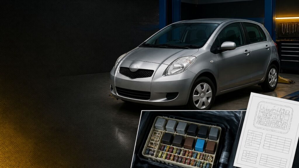
Checking and Replacing Fuses in Toyota Yaris Hatchback
If the headlights or other electrical components do not work, check the fuses. If any of the fuses are blown, they must be replaced.
- Turn the ignition switch and inoperative component off.
- Determine which fuse may be causing the problem. The lid of the fuse box shows the name of the circuit for each fuse.
- Pull a suspected fuse straight out and check it.
- If the fuse has blown, push a new fuse into the clip. Only install a fuse with the amperage rating designated on the fuse box lid.
Location of Fuse Boxes
Engine-Compartment Fuse and Relay Box
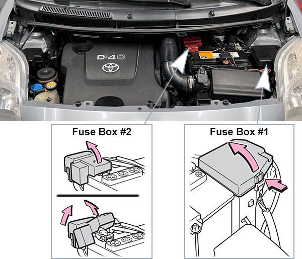
The main engine-compartment fuse box is located near the battery, usually toward the front or side of the engine bay. Its exact position can vary slightly depending on the engine, market, and left-hand-drive or right-hand-drive configuration.
This box contains fuses and relays for several high-current or engine-related systems. These may include the engine control system, radiator fan, starter circuit, fuel injection, headlights, horn, charging system, and other electrical equipment. The exact fuse and relay assignments should be checked against the vehicle-specific fuse diagram.
How to access the engine-bay box
- Park the vehicle on a level surface and switch off the ignition.
- Open the bonnet and secure it properly.
- Locate the rectangular fuse box close to the battery.
- Release the retaining clips or tabs on the fuse-box cover.
- Lift the cover carefully without forcing it.
The underside of the cover may contain a basic fuse diagram or identification markings. Compare these markings with the supplied fuse and relay diagram before removing anything. Some versions also include a fuse puller inside the cover or in the fuse box.
The relays in this area may be larger square or rectangular components than the blade fuses. Do not remove a relay unnecessarily, because relays can be difficult to identify by appearance alone. Use the relay diagram to confirm the correct component.
Interior Fuse Box Location
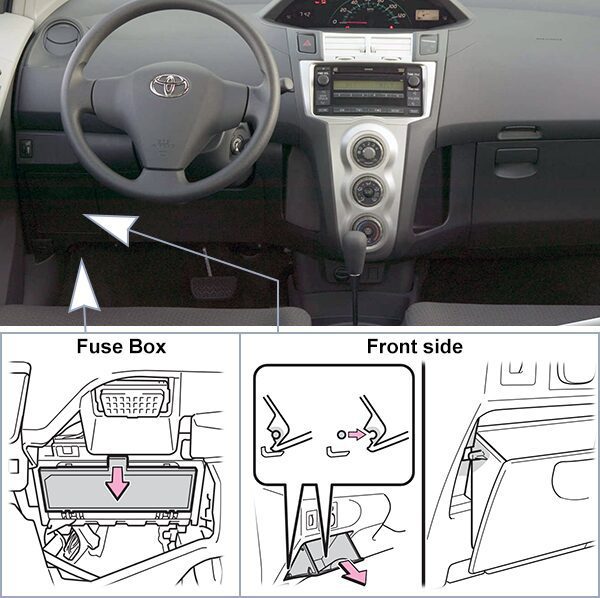
The second main fuse box is located inside the passenger compartment, underneath the dashboard on the driver’s side. It is positioned low in the instrument-panel area, close to the steering column and lower dashboard trim. On right-hand-drive vehicles, the location is mirrored accordingly.
This interior fuse box generally protects convenience and cabin circuits. Depending on equipment and market, it may contain fuses for the interior lights, instrument cluster, audio system, power outlets, windshield wipers, power windows, central locking, air conditioning, and other body-control functions.
How to access the interior fuse box
- Turn off the ignition and remove the key.
- Open the driver’s door to improve access.
- Look underneath the dashboard near the steering wheel.
- Remove the small access cover or lower trim panel.
- Release the panel carefully from its clips and set it aside.
Some versions have a simple removable cover, while others may require the lower dashboard panel to be unclipped. Avoid pulling on wiring or trim panels with excessive force. Plastic clips can become brittle, especially on older vehicles.
Once the cover is removed, the blade fuses should be visible. Use the fuse diagram to match the fuse number and amperage with the affected electrical circuit. The diagram may also identify relays located in or near the interior junction block.
Relay Locations
The Toyota Yaris XP90 does not normally have a separate relay box in the luggage compartment. Most accessible relays are housed in one of two areas:
- The engine-room fuse and relay box near the battery
- The interior fuse or junction block beneath the dashboard
Some relays are integrated into the interior junction block or engine-room relay block and are not intended to be replaced individually. Equipment levels and regional specifications can change the number and position of relays, so always confirm the location using the correct relay diagram for the vehicle.
A relay may look similar to another relay but have a different internal configuration. Never swap relays unless the part number, terminal arrangement, and diagram confirm that they are compatible. If a relay is suspected to be faulty, testing or replacement by a qualified technician may be safer than repeated substitution.
Fuse Box Diagrams
2006-2007
Engine Compartment Fuse Box #1
List of fuses in the Fuse Box #1 (2006-2007)
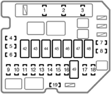
| № | Fuse | A | Function |
|---|---|---|---|
| 1 | AM2 | 15A | Starting system, multiport fuel injection system / sequential multiport fuel injection system |
| 2 | HORN | 10A | Horn |
| 3 | EFI | 20A | Multiport fuel injection system / sequential multiport fuel injection system |
| 4 | SPARE | 30A | Spare fuse |
| 5 | SPARE | 15A | Spare fuse |
| 6 | SPARE | 10A | Spare fuse |
| 7 | FR DEF | 20A | No circuit |
| 8 | ABS2/VSC2 | 30A | Anti-lock brake system |
| 9 | H-LP MAIN | 30A | No circuit |
| 10 | ST | 30A | Starting system |
| 11 | S-LOCK | 20A | No circuit |
| 12 | DOME | 15A | Interior light, personal lights, theft deterrent system, audio system, wireless remote control system |
| 13 | ECU-B | 7.5A | Engine immobilizer system, daytime running light system, front passenger occupant classification system, power windows, door lock system, theft deterrent system, meter and gauge |
| 14 | ALT-S | 7.5A | Charging system |
| 15 | ETCS | 10A | Multiport fuel injection system / sequential multiport fuel injection system, electronic throttle control system |
| 16 | HAZ | 10A | Turn signal lights, emergency flashers |
| 17 | H-LP RH / H-LP LO RH | 10A | Right-hand headlight |
| 18 | H-LP LH / H-LP LO LH | 10A | Left-hand headlight |
| 19 | EFI2 | 10A | Multiport fuel injection system / sequential multiport fuel injection system |
| 42 | HTR SUB2 | 40A | Air conditioning system |
| 43 | EPS | 50A | Electric power steering system |
| 44 | ABS1/VSC1 | 50A | Anti-lock brake system |
| 45 | HTR | 40A | Air conditioning system |
| 46 | RDI | 30A | Electric cooling fan |
| 47 | HTR SUB1 | 30A | Air conditioning system |
| 48 | H-LP CLN/PWR HTR | 30A | No circuit |
| 49 | AMT | 50A | No circuit |
Engine Compartment Fuse Box #2
List of fuses in the Fuse Box #2 (2006-2007)
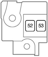
| № | Fuse | A | Function |
|---|---|---|---|
| 52 | ALT | 120A | Charging system, “HTR SUB2”, “EPS”, “ABS1/VSC1”, “HTR”, “ABS2/VSC2”, “HTR SUB1”, “RDI”, “DEF”, “FR FOG”, “OBD2”, “D/L”, “STOP” and “AM1” fuses |
| 53 | MAIN | 60A | “EFI”, “HORN”, “AM2”, “ALT-S”, “DOME”, “ST”, “ECU-B”, “ETCS”, “HAZ”, “H-LP LH/H-LP LO LH” and “H-LP RH/H-LP LO RH” fuses |
Instrument Panel Fuse Box
List of fuses in the instrument panel (2006-2007)
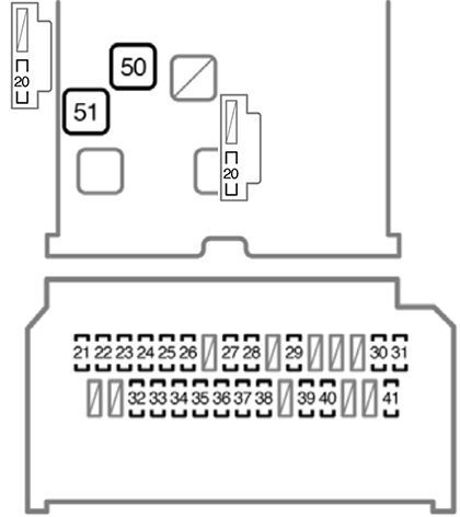
| № | Fuse | A | Function |
|---|---|---|---|
| 20 | ACC2 | 7.5A | Shift lock system |
| 21 | TAIL | 10A | Side marker lights, parking lights, tail lights, license plate lights, multiport fuel injection system / sequential multiport fuel injection system |
| 22 | PANEL1 | 7.5A | Illuminations, instrument panel light control, meter and gauge |
| 23 | A/C | 7.5A | Rear window defogger, air conditioning system |
| 24 | D DOOR | 20A | No circuit |
| 25 | RL DOOR | 20A | Rear passenger’s power window (left side) |
| 26 | RR DOOR | 20A | Rear passenger’s power window (right side) |
| 27 | CIG | 15A | Power outlet |
| 28 | ACC | 7.5A | Door lock system, outside rear view mirrors, audio system |
| 29 | ID/UP/MIR HTR | 10A | Multiport fuel injection system / sequential multiport fuel injection system |
| 30 | IGN | 7.5A | Multiport fuel injection system / sequential multiport fuel injection system, engine immobilizer system, SRS airbag system, front passenger occupant classification system |
| 31 | MET | 7.5A | Meter and gauge |
| 32 | WIP | 25A | Windshield wiper |
| 33 | RR WIP | 15A | Rear wiper |
| 34 | WSH | 15A | Windshield wiper and rear wiper |
| 35 | ECU-IG | 10A | Daytime running light system, anti-lock brake system, electric power steering system, power windows, door lock system, theft deterrent system, electric cooling fan |
| 36 | GAUGE | 10A | Charging system, turn signal lights, emergency flashers, buck-up lights, instrument panel light control, shift lock system, rear window defogger, air conditioning system, automatic transmission system |
| 37 | OBD2 | 7.5A | On-board diagnosis system |
| 38 | STOP | 10A | Stop lights, high mounted stop light, multiport fuel injection system / sequential multiport fuel injection system, shift lock system, anti-lock brake system |
| 39 | D/L | 25A | Door lock system |
| 40 | FR FOG | 15A | Front fog lights |
| 41 | AM1 | 25A | Multiport fuel injection system / sequential multiport fuel injection system |
| 50 | DEF | 30A | Rear window defogger |
| 51 | PWR | 30A | Power windows |
2008
Engine Compartment Fuse Box #1
List of fuses in the Fuse Box #1 (2008)
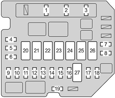
| № | Fuse | A | Circuit |
|---|---|---|---|
| 1 | AM2 | 15A | Starting system, multiport fuel injection system / sequential multiport fuel injection system |
| 2 | HORN | 10A | Horn |
| 3 | EFI | 20A | Multiport fuel injection system / sequential multiport fuel injection system |
| 4 | SPARE | 30A | Spare fuse |
| 5 | SPARE | 15A | Spare fuse |
| 6 | SPARE | 10A | Spare fuse |
| 7 | FR DEF | 20A | No circuit |
| 8 | ABS2/VSC2 | 30A | Anti-lock brake system |
| 9 | H-LP MAIN | 30A | No circuit |
| 10 | ST | 30A | Starting system |
| 11 | S-LOCK | 20A | No circuit |
| 12 | DOME | 15A | Interior light, personal lights, theft deterrent system, audio system, wireless remote control system |
| 13 | ECU-B | 7.5A | Engine immobilizer system, daytime running light system, front passenger occupant classification system, power windows, door lock system, theft deterrent system, meter and gauge |
| 14 | ALT-S | 7.5A | Charging system |
| 15 | ETCS | 10A | Multiport fuel injection system / sequential multiport fuel injection system, electronic throttle control system |
| 16 | HAZ | 10A | Turn signal lights, emergency flashers |
| 17 | H-LP RH / H-LP LO RH | 10A | Right-hand headlight |
| 18 | H-LP LH / H-LP LO LH | 10A | Left-hand headlight |
| 19 | EFI2 | 10A | Multiport fuel injection system / sequential multiport fuel injection system |
| 20 | HTR SUB2 | 40A | Air conditioning system |
| 21 | EPS | 50A | Electric power steering system |
| 22 | ABS1/VSC1 | 50A | Anti-lock brake system |
| 23 | HTR | 40A | Air conditioning system |
| 24 | RDI | 30A | Electric cooling fan |
| 25 | HTR SUB1 | 30A | Air conditioning system |
| 26 | H-LP CLN / PWR HTR | 30A | No circuit |
| 27 | AMT | 50A | No circuit |
Engine Compartment Fuse Box #2
List of fuses in the Fuse Box #2 (2008)
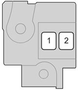
| № | Fuse | A | Circuit |
|---|---|---|---|
| 1 | ALT | 120A | Charging system, HTR SUB2, EPS, ABS1/VSC1, HTR, ABS2/VSC2, HTR SUB1, RDI, DEF, FR FOG, OBD2, D/L, POWER, RR DOOR, RL DOOR, STOP and AM1 |
| 2 | MAIN | 60A | EFI, HORN, AM2, ALT-S, DOME, ST, ECU-B, ETCS, HAZ, H-LP LH/ H-LP LO LH and H-LP RH/H-LP LO RH fuses |
Instrument Panel Fuse Box
List of fuses in the instrument panel (2008)
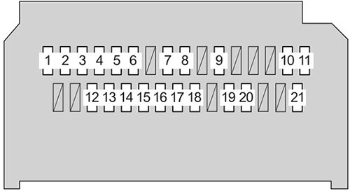
| № | Fuse | A | Circuit |
|---|---|---|---|
| 1 | TAIL | 10A | Side marker lights, parking lights tail lights, license plate lights, multiport fuel injection system / sequential multiport fuel injection system |
| 2 | PANEL 1 | 7.5A | Illuminations, instrument panel light control, meter and gauge |
| 3 | A/C | 7.5A | Rear window defogger, air conditioning system |
| 4 | D DOOR | 20A | No circuit |
| 5 | RL DOOR | 20A | Rear passenger’s power window (left side) |
| 6 | RR DOOR | 20A | Rear passenger’s power window (right side) |
| 7 | CIG | 15A | Power outlet |
| 8 | ACC | 7.5A | Door lock system, outside rear view mirrors, audio system |
| 9 | ID/UP/MIR HTR | 10A | Multiport fuel injection system / sequential multiport fuel injection system |
| 10 | IGN | 7.5A | Multiport fuel injection system / sequential multiport fuel injection system, engine immobilizer system, SRS airbag system, front passenger occupant classification system |
| 11 | MET | 7.5A | Meter and gauge |
| 12 | WIP | 25A | Windshield wiper |
| 13 | RR WIP | 15A | Rear wiper |
| 14 | WSH | 15A | Windshield washer |
| 15 | ECU-IG | 10A | Daytime running light system, antilock brake system, electric power steering system, power windows, door lock system, theft deterrent system, electric cooling fan |
| 16 | GAUGE | 10A | Charging system, turn signal lights, emergency flashers, buck-up lights, instrument panel light control, shift lock system, rear window defogger, air conditioning system, automatic transmission system |
| 17 | OBD2 | 7.5A | On-board diagnosis system |
| 18 | STOP | 10A | Stop lights, high mounted stoplight, multiport fuel injection system / sequential multiport fuel injection system, shift lock system, anti-lock brake system |
| 19 | D/L | 25A | Door lock system |
| 20 | FR FOG | 15A | Front fog lights |
| 21 | AM1 | 25A | Multiport fuel injection system / sequential multiport fuel injection system |
Front side
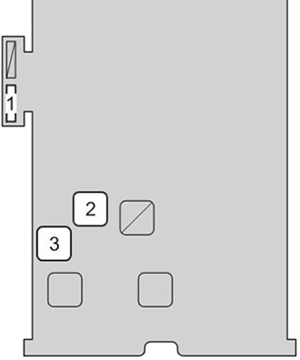
| № | Fuse | A | Circuit |
|---|---|---|---|
| 1 | ACC2 | 7.5A | Shift lock system |
| 2 | DEF | 30A | Rear window defogger |
| 3 | POWER | 30A | Power windows |
Conclusion
Understanding the fuse box location and relay locations on the Toyota Yaris Hatchback (XP90; 2006–2008) makes basic electrical troubleshooting faster and safer. The primary areas to check are the engine-compartment fuse and relay box near the battery and the interior fuse box beneath the dashboard on the driver’s side.
Always use the correct fuse rating, follow the fuse and relay diagram, and handle covers and wiring carefully. If a fuse continues to blow or the fault is difficult to identify, avoid repeated testing and consult a qualified automotive electrician or Toyota technician.