Learn about Ford F-650 / F-750 (2011-2015) fuse box and relay’s locations, functions, and maintenance tips for optimal vehicle electrical system.
The 2011–2015 Ford F-650 and F-750 medium-duty trucks are built to handle demanding commercial applications, from delivery routes to construction work. With engines like the Ford 6.7L Power Stroke diesel introduced during this generation, along with more sophisticated body and cab electronics, these trucks feature a more advanced electrical system than earlier F-650/F-750 models.
Fuses and relays remain the backbone of this electrical protection system, safeguarding circuits from overloads that could damage wiring, sensors, or onboard computers. For commercial truck owners and fleet operators, a malfunctioning fuse or relay can mean downtime, making it essential to know exactly where to look when troubleshooting electrical issues.
This guide covers the fuse box and relay locations for the 2011–2015 Ford F-650 and F-750, along with safe access methods and tips for identifying the correct fuse or relay using your truck’s diagrams.
MUST READ: DYI – How to Check Car Fuses?
(2011-2015) Ford F-650 / F-750 fuse box and relay with Diagram
WARNING
- Never replace a fuse with one that has a higher amperage rating.
- A fuse with a too-high amperage could damage the electrical part and cause a fire.
- On no account should fuses be repaired (e.g. patched up with tin foil or wire) as this may cause serious damage elsewhere in the electrical circuit or cause a fire.
- If a fuse blows repeatedly, do not keep replacing it. Instead, have the cause for the repeated short circuit or overload tracked and fixed.
- Terminal and harness assignments for individual connectors will vary depending on vehicle equipment level, model, and market.
Ford F-650 / F-750 (2011-2015) fuse assignment
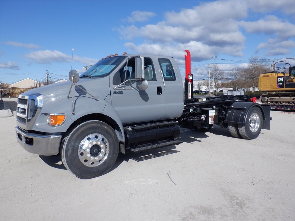
Ford F-650 / F-750 Year of production: 2011, 2012, 2013, 2014, 2015
Where Are the Fuse Boxes Located on the 2011–2015 Ford F-650/F-750?
These trucks typically include two primary fuse box locations; one under the hood and one inside the cab along with the possibility of additional auxiliary panels depending on the installed body and equipment.
1. Engine Compartment Fuse Box (Power Distribution Box)
The main power distribution box is located in the engine bay, generally mounted near the battery or firewall.
How to access it:
- Open the hood and locate the large black plastic cover near the battery or firewall area.
- Release the retaining clips or unscrew the fasteners securing the cover.
- Lift the cover to expose the fuses and relays inside.
This box protects high-amperage circuits such as the starter system, headlights, engine cooling fan, and glow plug relay on diesel-equipped trucks. Given the added complexity of the 6.7L Power Stroke’s electronics, this fuse box also houses relays tied to the engine control module and emissions-related components.
2. Interior Fuse Panel (Cab Fuse Box)
The interior fuse box is located inside the cab, typically under the dashboard on the driver’s side, similar in placement to Ford’s Super Duty pickup trucks from the same era.
How to access it:
- Locate the access panel under the dash, near the driver’s kick panel or to the left of the steering column.
- Remove the cover, which may be secured with clips, screws, or both depending on cab configuration.
- Once open, you’ll see the fuse block along with several interior relays.
This panel controls circuits such as interior lighting, radio, power windows and locks (if equipped), wipers, gauge cluster, and HVAC blower motor.
3. Auxiliary Relay and Fuse Panels (Upfitter Equipment)
Since F-650 and F-750 trucks are frequently upfitted with specialized bodies, box trucks, dump beds, flatbeds, or utility bodies, many include additional relay and fuse panels installed to power auxiliary equipment such as work lights, hydraulic systems, or PTO (power take-off) components.
Common locations for auxiliary panels:
- Behind the cab seat or in a dedicated storage compartment.
- Mounted along the frame rail near the rear of the cab.
- Inside control panels installed by the body manufacturer or upfitter.
Because these auxiliary electrical setups vary by application, always check your upfitter’s wiring documentation or physically inspect the cab and frame area for labeled panels when troubleshooting non-standard equipment.
4. Chassis and Transmission-Mounted Relays
Given the heavy-duty drivetrain options available on these trucks, certain relays, particularly those related to the transmission, PTO engagement, or air brake system, may be mounted directly on the frame rail rather than housed in a centralized fuse box.
How to access them:
- Inspect along the frame rail near the transmission housing or rear of the cab.
- These relays are typically enclosed in weatherproof connectors, and a wiring diagram is often necessary to correctly identify their function.
How to Identify the Right Fuse or Relay
Both the engine bay and interior fuse boxes include printed diagrams, usually located on the inside of the fuse box cover, detailing each fuse and relay by number, amperage rating, and function.
When troubleshooting:
- Match the malfunctioning component to its label on the printed diagram.
- Confirm the amperage rating before replacing any fuse to prevent further electrical issues.
- For relays tied to auxiliary equipment or upfitted systems, consult the equipment manufacturer’s documentation, since these often aren’t included in Ford’s standard fuse diagrams.
Safety Precautions Before Checking Fuses or Relays
- Turn off the ignition and remove the key before accessing any fuse or relay.
- For more involved electrical work, disconnect the negative battery terminal, many of these trucks use dual batteries, so disconnect both if instructed by service documentation.
- Use a fuse puller tool rather than metal tools to avoid sparking or damaging the fuse socket.
- Never install a replacement fuse with a higher amperage rating than specified, as this increases fire risk and can damage wiring.
- If a new fuse blows immediately after installation, stop and inspect the circuit for a short rather than continuing to replace fuses.
- When working near PTO systems, hydraulic lines, or auxiliary equipment relays, ensure all equipment is powered down and the parking brake is engaged before inspection.
Checking and Replacing Fuses in Ford F-650 / F-750
If electrical components in the vehicle are not working, a fuse may have blown. Blown fuses are identified by a broken wire within the fuse. Check the appropriate fuses before replacing any electrical components. To remove a fuse use the fuse puller tool provided on the fuse panel cover.
Location of Fuse Boxes
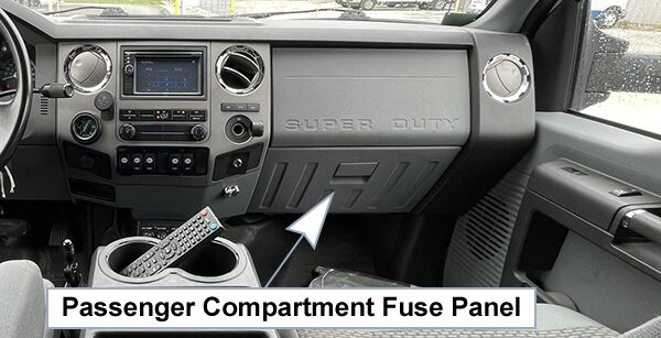
Passenger Compartment Fuse Panel:
The fuse box is located behind the passenger airbag cover and can be accessed through the glove box.
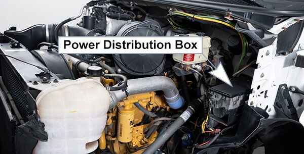
Power Distribution Box:
The power distribution box is located in the engine compartment. The power distribution box contains high-current fuses that protect your vehicle’s main electrical systems from overloads.
Fuse Box Diagrams
2011
Passenger Compartment Fuse Panel
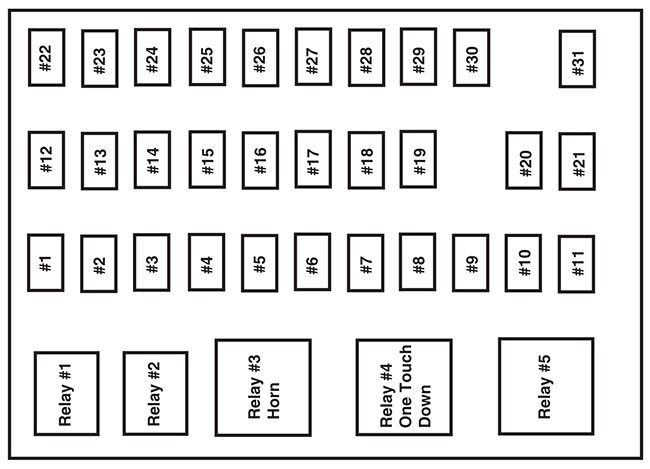
List of fuses in the passenger compartment fuse panel (2011)
| № | A | Fuse description |
|---|---|---|
| 1 | 20A | Horn |
| 2 | 15A | Flasher relay |
| 3 | 20A | Power point |
| 4 | 10A | Data Link Connector (DLC), Engine diagnostic connector, Parking brake warning |
| 5 | 15A | Run relay |
| 6 | – | Not used |
| 7 | – | Not used |
| 8 | 5A | Radio, GEM |
| 9 | 5A | Power window relay |
| 10 | 15A | Heated mirrors |
| 11 | 5A | Wiper and washer systems |
| 12 | 10A | Transmission shift selector |
| 13 | 20A | Radio, Power mirrors |
| 14 | 10A | Interior lamp relay |
| 15 | 10A | Interior lamp relay |
| 16 | 15A | High beams, Indicator |
| 17 | – | Not used |
| 18 | 5A | Dimmer switch, Interior lighting |
| 19 | 15A | Engine control |
| 20 | 5A | Starting system |
| 21 | 10A | DRL resistor |
| 22 | 15A | Air horn, Air suspension dump, Two-speed axle, Driver-controlled locking differential |
| 23 | 10A | Flasher relay |
| 24 | 15A | ABS relay, Fuel heater relay, Air dryer |
| 25 | 10A | Blower motor relay |
| 26 | 10A | Right-hand low beam headlight |
| 27 | – | Not used |
| 28 | 10A | Left-hand low beam headlight |
| 29 | 10A | Cluster, GEM |
| 30 | 15A | Allison electronic transmission |
| 31 | 15A | Mirror fold relay |
| Relay 1 | – | Interior lamps |
| Relay 2 | – | Not used |
| Relay 3 | – | Horn |
| Relay 4 | – | Not used |
| Relay 5 | – | Not used |
Power Distribution Box
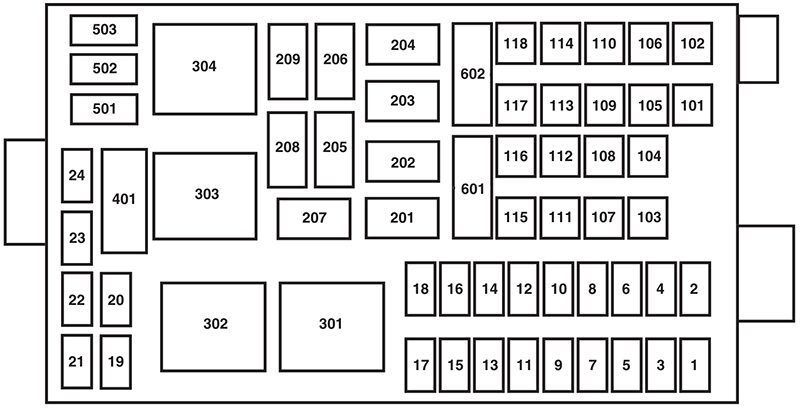
List of fuses in the power distribution box (2011)
| № | A | Fuse description |
|---|---|---|
| 1 | 20A | Upfitter switches (AUX 2 and AUX 4) |
| 2 | 30A | Power seat (driver) |
| 3 | 30A | Power seat (passenger) |
| 4 | 15A | Windshield washer relay, Washer pump motor |
| 5 | 5A | Brake warning switch (hydraulic brake only) |
| 6 | 20A | Upfitter switches (AUX 1 and AUX 3) |
| 7 | 15A | Brake pressure switches, ABS event relay |
| 8 | 20A | DEF (Urea), Line heaters |
| 9 | 20A | Ignition switch, Starter cutoff |
| 10 | 15A | Air tank moisture removal valve |
| 11 | 30A | Electric trailer brake |
| 12 | 20A | Passenger compartment fuse box 5 and 21 |
| 13 | 15A | Instrument cluster/Gateway module |
| 14 | 20A | Nitrogen oxide sensor |
| 15 | – | Not used |
| 16 | 5A | Bendix Air ABS |
| 17 | – | Not used |
| 18 | 10A | Fuel transfer pump |
| 19 | – | Not used |
| 20 | – | Not used |
| 21 | – | Not used |
| 22 | – | Not used |
| 23 | – | Not used |
| 24 | – | Not used |
| 101 | 30A | Bendix Air ABS relay (Air brake vehicles only) |
| Hydraulic brakes module (Hydraulic brake vehicles only) | ||
| 102 | 20A | Ignition switch |
| 103 | 20A | Ignition switch, Passenger compartment fuse box fuses 19, 29 and 30 |
| 104 | 20A | Power point |
| 105 | 20A | Power door lock switches |
| 106 | 30A | Main light switch, Multi-function switch |
| 107 | 50A | Passenger compartment fuse box fuses 1,2, 3, 4, 12, 13, 14 and 15 |
| 108 | 40A | Fuel heater |
| 109 | 40A | Power window |
| 110 | 30A | Windshield wiper |
| 111 | 30A | Body builder relay, Parking lamps |
| 112 | 40A | Blower motor |
| 113 | 30A | Heated seats, Air-Ride seat |
| 114 | 20A | Aftertreatment DCU |
| 115 | 20A | Ignition switch, Passenger compartment fuse box fuses 8, 9, 10 and 11 |
| 116 | 30A | Left/Right turn relays, Back-up lamp relay |
| 117 | 20A | Stoplamps |
| 118 | 60A | Hydraulic brake vehicles (Trailer tow package only) |
| 601 | 60A | Trailer socket |
| 602 | 60A | Air brake trailer tow fuse block |
| 30A | Hydraulic brakes pump motor 2 | |
| 201 | – | Windshield washer relay |
| 202 | – | Wiper high/low relay |
| 203 | – | Wiper run/park relay |
| 204 | – | Windshield wiper relay |
| 205 | – | Body builder relay, right turn |
| 206 | – | Body builder relay, left turn |
| 207 | – | ABS event relay (Hydraulic brake vehicles only) |
| 208 | – | Body builder relay, back-up lamps relay |
| 209 | – | Auxiliary stoplamp relay |
| 301 | – | Fuel heater/Fuel transfer pump relay |
| 302 | – | Body builder relay, parking lamps relay |
| 303 | – | Blower motor relay |
| 304 | – | DEF (Urea) line heaters relay |
| Individual maxi-fuse holder in engine compartment | ||
| 9925 | 30A | Hydraulic brakes pump motor 1 |
Relay Center
The relay center is located along the passenger side A-pillar on the right side of the footwell.
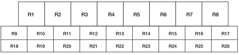
Relay Center (2011)
| № | Description |
|---|---|
| R1 | Spring applied hydraulic release warning chime module |
| R2 | A/C compressor clutch |
| R3 | Power Windows |
| R4 | Flasher (standard/LED) |
| R5 | Upfitter relay 1 |
| R6 | Upfitter relay 2 |
| R7 | Headlights |
| R8 | Spare |
| R9 | Upfitter relay 3 |
| R10 | Starter |
| R11 | DCU |
| R12 | Two-speed axle/Differential lock |
| R13 | Door lock |
| R14 | Air tank moisture valve |
| R15 | DRL #1 |
| R16 | Heated mirrors |
| R17 | Spare |
| R18 | Upfitter relay 4 |
| R19 | PRNDL display |
| R20 | Selective Catalyst Reduction (SCR) system (NOx) |
| R21 | Run |
| R22 | Door unlock |
| R23 | ABS warning indicator |
| R24 | DRL #2 |
| R25 | Park lights |
| R26 | Spare |
Trailer Tow Relays (If Equipped)
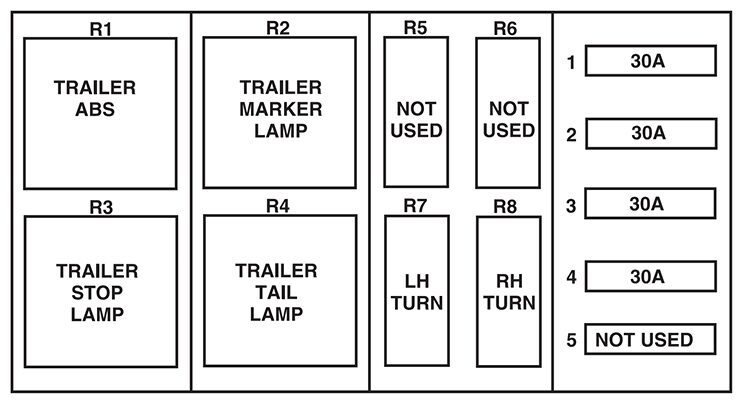
Trailer Tow Relays (If Equipped) (2011)
| № | A | Description |
|---|---|---|
| 1 | 30A* | Trailer tow ABS feed (non electric trailer brake vehicles only) |
| 2 | 30A* | Trailer tow park/marker lamps |
| 3 | 30A* | Trailer tow stop lamps |
| 4 | 30A* | Trailer tow turn/stop lamps (combined) |
| Trailer tow turn lamps (separate) | ||
| 5 | – | Not used |
| R1 | – | Trailer tow ABS relay (non electric trailer brake vehicles only) |
| R2 | – | Trailer tow marker lamp relay |
| R3 | – | Trailer tow stop lamp relay |
| R4 | – | Trailer tow tail lamp relay |
| R5 | – | Not used |
| R6 | – | Not used |
| R7 | – | Trailer tow left turn lamp relay |
| R8 | – | Trailer tow right turn lamp relay |
| *Maxi fiise | ||
Inline fuses
Your vehicle may have several inline fuses located in/on the battery cables located in the battery box depending on application.
- All Allison transmission equipped vehicles have a 10 Amp fuse located in the clean power cables located in the battery box.
- All vehicles have a 30 Amp fused located in the clean power cables located in the battery box.
- All vehicles equipped with an Eaton transmission have a 30 Amp fuse located in the clean power cables located in the battery box.
- All Hydraulic brake equipped vehicles have a 40 Amp fuse located in the clean power cables located in the battery box and in addition another 30 Amp fuse located in a fuse holder just above the power distribution center located in the vehicles engine compartment.
2012
Passenger Compartment Fuse Panel
List of fuses in the passenger compartment fuse panel (2012)
| № | A | Description |
|---|---|---|
| 1 | 20A | Horn |
| 2 | 15A | Flasher relay |
| 3 | 20A | Power point |
| 4 | 10A | Data Link Connector (DLC), Engine diagnostic connector, Parking brake warning |
| 5 | 15A | Run relay |
| 6 | – | Not used |
| 7 | – | Not used |
| 8 | 5A | Radio, GEM |
| 9 | 5A | Power window relay |
| 10 | 15A | Heated mirrors |
| 11 | 5A | Wiper and washer systems |
| 12 | 10A | Transmission shift selector |
| 13 | 20A | Radio/SYNC, Power mirrors |
| 14 | 10A | Interior lamp relay |
| 15 | 10A | Interior lamp relay |
| 16 | 15A | High beams, Indicator |
| 17 | – | Not used |
| 18 | 5A | Dimmer switch, Interior lighting |
| 19 | 15A | Engine control (diesel engine only) |
| 20 | 5A | Starting system |
| 21 | 10A | DRL resistor |
| 22 | 15A | Air horn, Air suspension dump, Two-speed axle, Driver-controlled locking differential |
| 23 | 10A | Flasher relay |
| 24 | 15A | Hydraulic brakes relay, Fuel heater relay (diesel engine only), Air dryer |
| 25 | 10A | Blower motor relay coil |
| 26 | 10A | Right-hand low beam headlight |
| 27 | – | Not used |
| 28 | 10A | Left-hand low beam headlight |
| 29 | 10A | Cluster, GEM |
| 30 | 15A | Allison electronic transmission |
| 31 | 15A | Mirror fold relay |
| Relay 1 | – | Interior lamps |
| Relay 2 | – | Not used |
| Relay 3 | – | Horn |
| Relay 4 | – | Not used |
| Relay 5 | Not used |
Power Distribution Box
List of fuses in the power distribution box (2012)
| № | A | Description |
|---|---|---|
| 1 | 20A | Upfitter switches (AUX 2 and AUX 4)/Trailer 12V socket pin |
| 2 | 30A | Power seat (driver) |
| 3 | 30A | Power seat (passenger) |
| 4 | 15A | Windshield washer relay, Washer pump motor |
| 5 | 5A | Brake warning switch (hydraulic brake only) |
| 6 | 20A | Upfitter switches (AUX 1 and AUX 3) |
| 7 | 15A | Brake pressure switches, ABS event relay |
| 8 | 20A | DEF (Urea), Line heaters (diesel engine only) |
| 9 | 20A | Ignition switch, Starter cutoff |
| 10 | 15A | Air tank moisture removal valve |
| 11 | 30A | Electric trailer brake |
| 12 | 20A | Passenger compartment fuse box 5 and 21 |
| 13 | 15A | Instrument cluster/Gateway module |
| 14 | 20A | Nitrogen oxide sensor (diesel engine only) |
| 15 | – | Not used |
| 16 | 5A | Bendix Air ABS |
| 17 | – | Not used |
| 18 | 10A | Fuel transfer pump |
| 19 | 15A | Powertrain control module power 1 (gasoline engine only) |
| 20 | 10A | Powertrain control module power 2 (gasoline engine only) |
| 21 | 20A | Powertrain control module power 3 (gasoline engine only) |
| 22 | 20A | Powertrain control module power 4 (gasoline engine only) |
| 23 | – | Not used |
| 24 | 10A | Powertrain control module keep-alive power (gasoline engine only) |
| 101 | 30A | Bendix Air ABS relay (Air brake vehicles only) |
| Hydraulic brakes module (Hydraulic brake vehicles only) | ||
| 102 | 20A | Ignition switch |
| 103 | 20A | Ignition switch, Passenger compartment fuse box fuses 19, 29 and 30 |
| 104 | 20A | Power point |
| 105 | 20A | Power door lock switches |
| 106 | 30A | Main light switch, Multi-function switch |
| 107 | 50A | Passenger compartment fuse box fuses 1,2, 3, 4, 12, 13, 14 and 15 |
| 108 | 40A | Fuel heater (diesel engine only) |
| 20A | Fuel pump module (gasoline engine only) | |
| 109 | 40A | Power window |
| 110 | 30A | Windshield wiper |
| 111 | 30A | Body builder relay, Parking lamps |
| 112 | 40A | Blower motor |
| 113 | 30A | Heated seats, Air-Ride seat |
| 114 | 20A | Aftertreatment DCU |
| 115 | 20A | Ignition switch, Passenger compartment fuse box fuses 8, 9, 10 and 11 |
| 116 | 30A | Left/Right turn relays, Back-up lamp relay |
| 117 | 20A | Stoplamps |
| 118 | 60A | Hydraulic brake vehicles (Trailer tow package only) |
| 601 | 60A | Trailer socket |
| 602 | 60A | Air brake trailer tow fuse block |
| 30A | Hydraulic brakes pump motor 2 | |
| 201 | – | Windshield washer relay |
| 202 | – | Wiper high/low relay |
| 203 | – | Wiper run/park relay |
| 204 | – | Windshield wiper relay |
| 205 | – | Body builder relay, right turn |
| 206 | – | Body builder relay, left turn |
| 207 | – | ABS event relay (Hydraulic brake vehicles only) |
| 208 | – | Body builder relay, back-up lamps relay |
| 209 | – | Auxiliary stoplamp relay |
| 301 | – | Fuel heater/Fuel transfer pump relay (diesel engine only) |
| – | Fuel pump module (gasoline engine only) | |
| 302 | – | Body builder relay, parking lamps relay |
| 303 | – | Blower motor relay |
| 304 | – | DEF (Urea) line heaters relay (diesel engine only) |
| – | Powertrain control module power VPWR1 (gasoline engine only) | |
| Individual maxi-fuse holder in engine compartment | ||
| 9925 | 30A | Hydraulic brakes pump motor 1 |
Relay Center
The relay center is located along the passenger side A-pillar on the right side of the footwell.
Relay Center (2012)
| № | Description |
|---|---|
| R1 | Spring applied hydraulic release warning chime module or PCM power VPWR 2, 3 and 4 |
| R2 | A/C compressor clutch |
| R3 | Power Windows |
| R4 | Flasher (standard/LED) |
| R5 | Upfitter relay 1 |
| R6 | Upfitter relay 2 |
| R7 | Headlights |
| R8 | Spare |
| R9 | Upfitter relay 3 |
| R10 | Starter |
| R11 | DCU (diesel engine only) |
| R12 | Two-speed axle/Differential lock |
| R13 | Door lock |
| R14 | Air tank moisture valve |
| R15 | DRL #1 |
| R16 | Heated mirrors |
| R17 | Spare |
| R18 | Upfitter relay 4 |
| R19 | Shift interlock/EPRNDL display |
| R20 | Selective Catalyst Reduction (SCR) system (NOx) (diesel engine only) |
| R21 | Run |
| R22 | Door unlock |
| R23 | ABS warning indicator |
| R24 | DRL #2 |
| R25 | Park lights |
| R26 | Spare |
Trailer Tow Relays (If Equipped)
Trailer Tow Relays (If Equipped) (2012)
| № | A | Description |
|---|---|---|
| 1 | 30A* | Trailer tow ABS feed (non electric trailer brake vehicles only) |
| 2 | 30A* | Trailer tow park/marker lamps |
| 3 | 30A* | Trailer tow stop lamps |
| 4 | 30A* | Trailer tow turn/stop lamps (combined) |
| Trailer tow turn lamps (separate) | ||
| 5 | – | Not used |
| R1 | – | Trailer tow ABS relay (non electric trailer brake vehicles only) |
| R2 | – | Trailer tow marker lamp relay |
| R3 | – | Trailer tow stop lamp relay |
| R4 | – | Trailer tow tail lamp relay |
| R5 | – | Not used |
| R6 | – | Not used |
| R7 | – | Trailer tow left turn lamp relay |
| R8 | – | Trailer tow right turn lamp relay |
| *Maxi fuse | ||
Inline fuses
Your vehicle may have several inline fuses located in/on the battery cables located in the battery box depending on application.
- All Allison transmission equipped vehicles have a 10 Amp fuse located in the clean power cables located in the battery box.
- All vehicles have a 30 Amp fused located in the clean power cables located in the battery box.
- All vehicles equipped with an Eaton transmission have a 30 Amp fuse located in the clean power cables located in the battery box.
- All Hydraulic brake equipped vehicles have a 40 Amp fuse located in the clean power cables located in the battery box and in addition another 30 Amp fuse located in a fuse holder just above the power distribution center located in the vehicles engine compartment.
2013
Passenger Compartment Fuse Panel
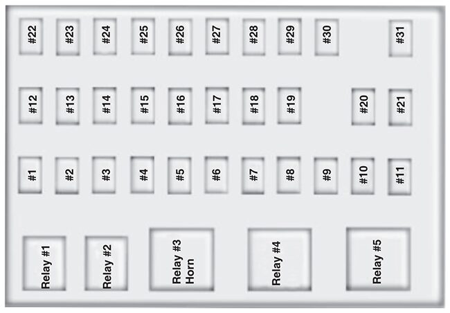
List of fuses in the passenger compartment fuse panel (2013)
| № | A | Protected Circuits |
|---|---|---|
| 1 | 20A | Horn |
| 2 | 15A | Flasher relay |
| 3 | 20A | Power point |
| 4 | 10A | Data Link Connector (DLC), Engine diagnostic connector, Parking brake warning |
| 5 | 15A | Run relay |
| 6 | – | Not used |
| 7 | – | Not used |
| 8 | 5A | Radio, GEM |
| 9 | 5A | Power window relay |
| 10 | 15A | Heated mirrors |
| 11 | 5A | Wiper and washer systems |
| 12 | 10A | Transmission shift selector |
| 13 | 20A | Radio/SYNC, Power mirrors |
| 14 | 10A | Interior lamp relay |
| 15 | 10A | Interior lamp relay |
| 16 | 15A | High beams, Indicator |
| 17 | – | Not used |
| 18 | 5A | Dimmer switch, Interior lighting |
| 19 | 15A | Engine control (diesel engine only) |
| 20 | 5A | Starting system |
| 21 | 10A | DRL resistor |
| 22 | 15A | Air horn, Air suspension dump, Two-speed axle, Driver-controlled locking differential |
| 23 | 10A | Flasher relay |
| 24 | 15A | Hydraulic brakes relay, Fuel heater relay (diesel engine only), Air dryer |
| 25 | 10A | Blower motor relay coil |
| 26 | 10A | Right-hand low beam headlight |
| 27 | – | Not used |
| 28 | 10A | Left-hand low beam headlight |
| 29 | 10A | Cluster, GEM |
| 30 | 15A | Allison electronic transmission |
| 31 | 15A | Mirror fold relay |
| Relay 1 | – | Interior lamps |
| Relay 2 | – | Not used |
| Relay 3 | – | Horn |
| Relay 4 | – | Not used |
| Relay 5 | – | Not used |
Power Distribution Box
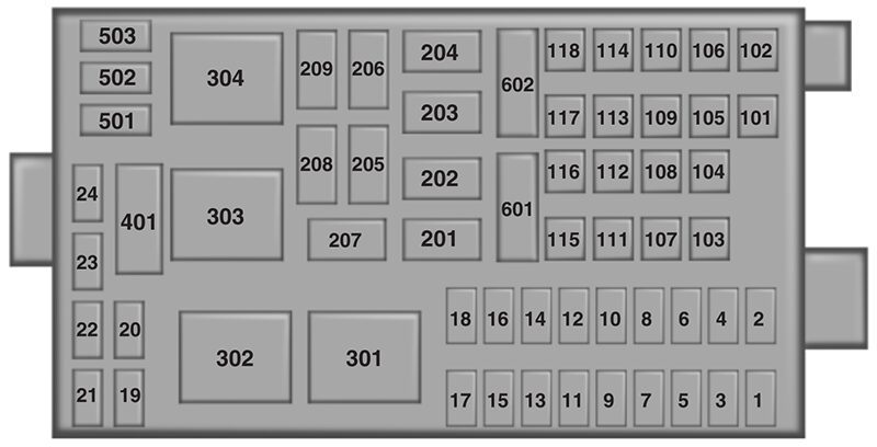
List of fuses in the power distribution box (2013)
| № | A | Protected Circuits |
|---|---|---|
| 1 | 20A | Upfitter switches (AUX 2 and AUX 4)/Trailer 12V socket pin |
| 2 | 30A | Power seat (driver) |
| 3 | 30A | Power seat (passenger) |
| 4 | 15A | Windshield washer relay, Washer pump motor |
| 5 | 5A | Brake warning switch (hydraulic brake vehicles only) |
| 6 | 20A | Upfitter switches (AUX 1 and AUX 3) |
| 7 | 15A | Brake pressure switches, ABS event relay |
| 8 | 20A | DEF (Urea) line heaters (diesel engine only) |
| 9 | 20A | Ignition switch, Starter cutoff |
| 10 | 15A | Air tank moisture removal valve |
| 11 | 30A | Electric trailer brake |
| 12 | 20A | Passenger compartment fuse box 5 and 21 |
| 13 | 15A | Instrument cluster/Gateway module |
| 14 | 20A | Nitrogen oxide sensor (diesel engine only) |
| 15 | – | Not used |
| 16 | 5A | Bendix Air ABS |
| 17 | – | Not used |
| 18 | 10A | Fuel transfer pump |
| 19 | 15A | Powertrain control module power 1 (gasoline engine only) |
| 20 | 10A | Powertrain control module power 2 (gasoline engine only) |
| 21 | 20A | Powertrain control module power 3 (gasoline engine only) |
| 22 | 20A | Powertrain control module power 4 (gasoline engine only) |
| 23 | – | Not used |
| 24 | 10A | Powertrain control module keep-alive power (gasoline engine only) |
| 101 | 30A | Bendix Air ABS relay (Air brake vehicles only) |
| Hydraulic brakes module (hydraulic brake vehicles only) | ||
| 102 | 20A | Ignition switch |
| 103 | 20A | Ignition switch, Passenger compartment fuse box fuses 19, 29 and 30 |
| 104 | 20A | Power point |
| 105 | 20A | Power door lock switches |
| 106 | 30A | Main light switch, Multi-function switch |
| 107 | 50A | Passenger compartment fuse box fuses 1,2, 3, 4, 12, 13, 14 and 15 |
| 108 | 40A | Fuel heater (diesel engine only) |
| 20A | Fuel pump module (gasoline engine only) | |
| 109 | 40A | Power window |
| 110 | 30A | Windshield wiper |
| 111 | 30A | Body builder relay, Parking lamps |
| 112 | 40A | Blower motor |
| 113 | 30A | Heated seats, Air-Ride seat |
| 114 | 20A | Aftertreatment DCU |
| 115 | 20A | Ignition switch, Passenger compartment fuse box fuses 8, 9, 10 and 11 |
| 116 | 30A | Left/Right turn relays, Back up lamp relay |
| 117 | 20A | Stop lamps |
| 118 | 60A | Hydraulic brake vehicles (trailer tow package only) |
| 601 | 60A | Trailer socket |
| 602 | 60A | Air brake trailer tow fuse block |
| 30A | Hydraulic brakes pump motor 2 | |
| 201 | – | Windshield washer relay |
| 202 | – | Wiper high/low relay |
| 203 | – | Wiper run/park relay |
| 204 | – | Windshield wiper relay |
| 205 | – | Body builder relay, right turn |
| 206 | – | Body builder relay, left turn |
| 207 | – | ABS event relay (hydraulic brake vehicles only) |
| 208 | – | Body builder relay, back up lamps relay |
| 209 | – | Auxiliary stop lamp relay |
| 301 | – | Fuel heater/Fuel transfer pump relay (diesel engine only) |
| – | Fuel pump module (gasoline engine only) | |
| 302 | – | Body builder relay, parking lamps relay |
| 303 | – | Blower motor relay |
| 304 | – | DEF (Urea) line heaters relay (diesel engine only) |
| – | Powertrain control module power VPWR1 (gasoline engine only) | |
| Individual Maxi Fuse Holder in Engine Compartment | ||
| 9925 | 30A | Hydraulic brakes pump motor 1 |
Relay Center
The relay center is located along the passenger side A-pillar on the right side of the footwell.
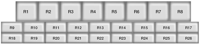
Relay Center (2013)
| № | Relay Description |
|---|---|
| R1 | Spring applied hydraulic release warning chime module or PCM power VPWR 2, 3 and 4 |
| R2 | A/C compressor clutch |
| R3 | Power Windows |
| R4 | Flasher (standard/LED) |
| R5 | Upfitter relay 1 |
| R6 | Upfitter relay 2 |
| R7 | Headlights |
| R8 | Spare |
| R9 | Upfitter relay 3 |
| R10 | Starter |
| R11 | DCU (diesel engine only) |
| R12 | Two-speed axle/Differential lock |
| R13 | Door lock |
| R14 | Air tank moisture valve |
| R15 | DRL #1 |
| R16 | Heated mirrors |
| R17 | Spare |
| R18 | Upfitter relay 4 |
| R19 | Shift interlock/EPRNDL display |
| R20 | Selective Catalyst Reduction (SCR) system (NOx) (diesel engine only) |
| R21 | Run |
| R22 | Door unlock |
| R23 | ABS warning indicator |
| R24 | DRL #2 |
| R25 | Park lights |
| R26 | Spare |
Trailer Tow Relays (If Equipped)
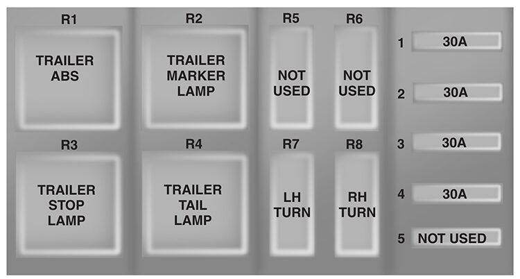
Trailer Tow Relays (If Equipped) (2013)
| № | A | Protected Circuits |
|---|---|---|
| 1 | 30A* | Trailer tow ABS feed (non electric trailer brake vehicles only) |
| 2 | 30A* | Trailer tow park/marker lamps |
| 3 | 30A* | Trailer tow stop lamps |
| 4 | 30A* | Trailer tow turn/stop lamps (combined) |
| Trailer tow turn lamps (separate) | ||
| 5 | – | Not used |
| R1 | – | Trailer tow ABS relay (non electric trailer brake vehicles only) |
| R2 | – | Trailer tow marker lamp relay |
| R3 | – | Trailer tow stop lamp relay |
| R4 | – | Trailer tow tail lamp relay |
| R5 | – | Not used |
| R6 | – | Not used |
| R7 | – | Trailer tow left turn lamp relay |
| R8 | – | Trailer tow right turn lamp relay |
| *Maxi fuse | ||
Inline fuses
Your vehicle may have several inline fuses located in/on the battery cables located in the battery box depending on application.
- All Allison transmission equipped vehicles have a 10 Amp fuse located in the clean power cables located in the battery box.
- All vehicles have a 30 Amp fused located in the clean power cables located in the battery box.
- All vehicles equipped with an Eaton transmission have a 30 Amp fuse located in the clean power cables located in the battery box.
- All Hydraulic brake equipped vehicles have a 40 Amp fuse located in the clean power cables located in the battery box and in addition another 30 Amp fuse located in a fuse holder just above the power distribution center located in the vehicles engine compartment.
2015
Passenger Compartment Fuse Panel
List of fuses in the passenger compartment fuse panel (2015)
| № | A | Protected Circuits |
|---|---|---|
| 1 | 20A | Horn |
| 2 | 15A | Flasher relay |
| 3 | 20A | Power point |
| 4 | 10A | Data Link Connector (DLC), Engine diagnostic connector, Parking brake warning |
| 5 | 15A | Run relay |
| 6 | – | Not used |
| 7 | – | Not used |
| 8 | 5A | Radio, GEM |
| 9 | 5A | Power window relay |
| 10 | 15A | Heated mirrors |
| 11 | 5A | Wiper and washer systems |
| 12 | 10A | Transmission shift selector |
| 13 | 20A | Radio/SYNC, Power mirrors |
| 14 | 10A | Interior lamp relay |
| 15 | 10A | Interior lamp relay |
| 16 | 15A | High beams, Indicator |
| 17 | – | Not used |
| 18 | 5A | Dimmer switch, Interior lighting |
| 19 | 15A | Engine control (diesel engine only) |
| 20 | 5A | Starting system |
| 21 | 10A | DRL resistor |
| 22 | 15A | Air horn, Air suspension dump, Two-speed axle, Driver-controlled locking differential |
| 23 | 10A | Flasher relay |
| 24 | 15A | Hydraulic brakes relay, Fuel heater relay (diesel engine only), Air dryer |
| 25 | 10A | Blower motor relay coil |
| 26 | 10A | Right-hand low beam headlight |
| 27 | – | Not used |
| 28 | 10A | Left-hand low beam headlight |
| 29 | 10A | Cluster, GEM |
| 30 | 15A | Allison electronic transmission |
| 31 | 15A | Mirror fold relay |
| Relay 1 | – | Interior lamps |
| Relay 2 | – | Not used |
| Relay 3 | – | Horn |
| Relay 4 | – | Not used |
| Relay 5 | Not used |
Power Distribution Box
List of fuses in the power distribution box (2015)
| № | A | Protected Circuits |
|---|---|---|
| 1 | 20A | Upfitter switches (AUX 2 and AUX 4)/Trailer 12V socket pin |
| 2 | 30A | Power seat (driver) |
| 3 | 30A | Power seat (passenger) |
| 4 | 15A | Windshield washer relay, Washer pump motor |
| 5 | 5A | Brake warning switch (hydraulic brake vehicles only) |
| 6 | 20A | Upfitter switches (AUX 1 and AUX 3) |
| 7 | 15A | Brake pressure switches, ABS event relay |
| 8 | 20A | DEF (Urea) line heaters (diesel engine only) |
| 9 | 20A | Ignition switch, Starter cutoff |
| 10 | 15A | Air tank moisture removal valve |
| 11 | 30A | Electric trailer brake |
| 12 | 20A | Passenger compartment fuse box 5 and 21 |
| 13 | 15A | Instrument cluster/Gateway module |
| 14 | 20A | Nitrogen oxide sensor (diesel engine only) |
| 15 | – | Not used |
| 16 | 5A | Bendix Air ABS |
| 17 | – | Not used |
| 18 | 10A | Fuel transfer pump |
| 19 | 15A | Powertrain control module power 1 (gasoline engine only) |
| 20 | 10A | Powertrain control module power 2 (gasoline engine only) |
| 21 | 20A | Powertrain control module power 3 (gasoline engine only) |
| 22 | 20A | Powertrain control module power 4 (gasoline engine only) |
| 23 | – | Not used |
| 24 | 10A | Powertrain control module keep-alive power (gasoline engine only) |
| 101 | 30A | Bendix Air ABS relay (Air brake vehicles only) |
| Hydraulic brakes module (hydraulic brake vehicles only) | ||
| 102 | 20A | Ignition switch |
| 103 | 20A | Ignition switch, Passenger compartment fuse box fuses 19, 29 and 30 |
| 104 | 20A | Power point |
| 105 | 20A | Power door lock switches |
| 106 | 30A | Main light switch, Multi-function switch |
| 107 | 50A | Passenger compartment fuse box fuses 1,2, 3, 4, 12, 13, 14 and 15 |
| 108 | 40A | Fuel heater (diesel engine only) |
| 20A | Fuel pump module (gasoline engine only) | |
| 109 | 40A | Power window |
| 110 | 30A | Windshield wiper |
| 111 | 30A | Body builder relay, Parking lamps |
| 112 | 40A | Blower motor |
| 113 | 30A | Heated seats, Air-Ride seat |
| 114 | – | Not used |
| 115 | 20A | Ignition switch, Passenger compartment fuse box fuses 8, 9, 10 and 11 |
| 116 | 30A | Left/Right turn relays, Back up lamp relay |
| 117 | 20A | Stop lamps |
| 118 | 60A | Hydraulic brake vehicles (trailer tow package only) |
| 601 | 60A | Trailer socket |
| 602 | 60A | Air brake trailer tow fuse block |
| 201 | – | Windshield washer relay |
| 202 | – | Wiper high/low relay |
| 203 | – | Wiper run/park relay |
| 204 | – | Windshield wiper relay |
| 205 | – | Body builder relay, right turn |
| 206 | – | Body builder relay, left turn |
| 207 | – | ABS event relay (hydraulic brake vehicles only) |
| 208 | – | Body builder relay, back up lamps relay |
| 209 | – | Auxiliary stop lamp relay |
| 301 | – | Fuel heater/Fuel transfer pump relay (diesel engine only) |
| – | Fuel pump module (gasoline engine only) | |
| 302 | – | Body builder relay, parking lamps relay |
| 303 | – | Blower motor relay |
| 304 | – | DEF (Urea) line heaters relay (diesel engine only) |
| – | Powertrain control module power VPWR1 (gasoline engine only) | |
| Individual Maxi Fuse Holder in Engine Compartment | ||
| 9925 | 30A | Hydraulic brakes pump motor 1 |
Relay Center
The relay center is located along the passenger side A-pillar on the right side of the footwell.
Relay Center (2015)
| № | Relay Description |
|---|---|
| R1 | Spring applied hydraulic release warning chime module or PCM power VPWR 2, 3 and 4 |
| R2 | A/C compressor clutch |
| R3 | Power Windows |
| R4 | Flasher (standard/LED) |
| R5 | Upfitter relay 1 |
| R6 | Upfitter relay 2 |
| R7 | Headlights |
| R8 | Cummins starter lockout |
| R9 | Upfitter relay 3 |
| R10 | Starter |
| R11 | DCU (diesel engine only) |
| R12 | Two-speed axle/Differential lock |
| R13 | Door lock |
| R14 | Air tank moisture valve |
| R15 | DRL #1 |
| R16 | Heated mirrors |
| R17 | Spare |
| R18 | Upfitter relay 4 |
| R19 | Shift interlock/EPRNDL display |
| R20 | Selective Catalyst Reduction (SCR) system (NOx) (diesel engine only) |
| R21 | Run |
| R22 | Door unlock |
| R23 | ABS warning indicator |
| R24 | DRL #2 |
| R25 | Park lights |
| R26 | Spare |
Trailer Tow Relays (If Equipped)
Trailer Tow Relays (If Equipped) (2015)
| № | A | Protected Circuits |
|---|---|---|
| 1 | 30A* | Trailer tow ABS feed (non electric trailer brake vehicles only) |
| 2 | 30A* | Trailer tow park/marker lamps |
| 3 | 30A* | Trailer tow stop lamps |
| 4 | 30A* | Trailer tow turn/stop lamps (combined) |
| Trailer tow turn lamps (separate) | ||
| 5 | – | Not used |
| R1 | – | Trailer tow ABS relay (non electric trailer brake vehicles only) |
| R2 | – | Trailer tow marker lamp relay |
| R3 | – | Trailer tow stop lamp relay |
| R4 | – | Trailer tow tail lamp relay |
| R5 | – | Not used |
| R6 | – | Not used |
| R7 | – | Trailer tow left turn lamp relay |
| R8 | – | Trailer tow right turn lamp relay |
| *Maxi fuse | ||
Inline Fuses
Your vehicle may have several inline fuses located in, or on, the battery cables located in the battery box (depending on application).
- All vehicles equipped with an Allison transmission have a 10 amp fuse located in the clean power cables located in the battery box.
- All vehicles have a 30 amp fuse located in the clean power cables located in the battery box.
- All vehicles equipped with hydraulic brakes have a 40 amp fuse located in the clean power cables located in the battery box. In addition, another 30 amp fuse is located in a fuse holder just above the power distribution center located in the vehicle’s engine compartment.
Conclusion
The 2011–2015 Ford F-650 and F-750 combine standard Ford fuse box design with the added complexity of commercial-grade equipment and upfitted body systems. Knowing where your primary fuse boxes are located along with any auxiliary panels specific to your truck’s configuration, makes diagnosing electrical issues significantly more manageable, helping minimize downtime.
Always handle fuses and relays carefully, confirm amperage ratings before replacing any component, and consult upfitter documentation for equipment-specific relays not covered by Ford’s standard diagrams. If electrical issues persist or involve complex systems like the PTO, transmission relays, or emissions-related components, consulting a technician experienced with medium-duty Ford trucks is the safest and most efficient next step.