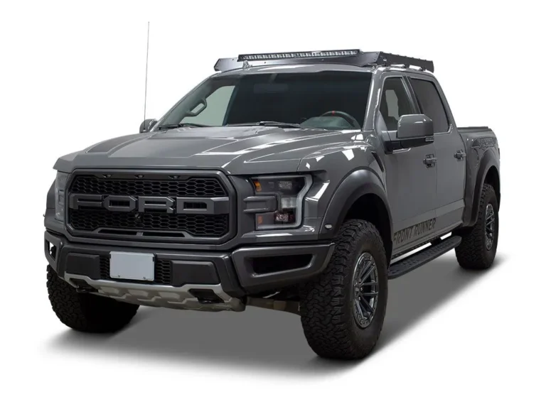
Learn about Ford F-250 / F-350 / F-450 / F-550 (2017-2019) fuse box and relay’s locations, functions, and maintenance tips for optimal vehicle electrical system.
The 2017–2019 Ford Super Duty lineup brought major updates, including a high-strength aluminum body and revised electrical architecture. With these changes came updated fuse box designs and relay layouts compared to earlier Super Duty generations. If you own an F-250, F-350, F-450, or F-550 from this model range, understanding your truck’s fuse box location and relay diagram is key to solving everyday electrical problems quickly.
Fuses and relays act as protective checkpoints for your truck’s electrical system. Fuses prevent circuit overloads by breaking the connection when too much current flows through, while relays act as switches that control higher-power components like fans, fuel pumps, and lighting systems. When something electrical stops working, a power outlet, taillight, or infotainment screen, a blown fuse or faulty relay is often the culprit.
This guide covers where to find the fuse boxes and relay panels on the 2017–2019 Ford Super Duty trucks, how to access them safely, and how to use the printed diagrams to identify the right component for your issue.
MUST READ: DYI – How to Check Car Fuses?
(2017-2019) Ford F-250 / F-350 / F-450 / F-550 fuse box and relay with Diagram
WARNING
- Never replace a fuse with one that has a higher amperage rating.
- A fuse with a too-high amperage could damage the electrical part and cause a fire.
- On no account should fuses be repaired (e.g. patched up with tin foil or wire) as this may cause serious damage elsewhere in the electrical circuit or cause a fire.
- If a fuse blows repeatedly, do not keep replacing it. Instead, have the cause for the repeated short circuit or overload tracked and fixed.
- Terminal and harness assignments for individual connectors will vary depending on vehicle equipment level, model, and market.
Ford F-250 / F-350 / F-450 / F-550 (2017-2019) fuse assignment
Ford F-250 / F-350 / F-450 / F-550 Year of production: 2017, 2018, 2019
Where Are the Fuse Boxes Located on the 2017–2019 Ford Super Duty?
Like previous generations, these trucks use two primary fuse box locations, one in the engine bay and one inside the cabin. However, the redesigned body and updated electrical system mean slightly different access points and component layouts compared to 2011–2016 models.
1. Engine Compartment Fuse Box (Power Distribution Box)
The main power distribution box is located in the engine compartment, mounted near the back of the bay, close to the firewall on the driver’s side.
How to access it:
- Open the hood and locate the large black rectangular cover near the firewall.
- Release the retaining clips along the edges of the cover, most 2017+ models use snap-lock tabs rather than screws, making them easier to open by hand.
- Lift the cover away carefully to expose the fuses and relays underneath.
This box protects high-draw components such as the headlights, engine cooling fan, horn relay, glow plug system (on diesel models), and starter circuit. Since this fuse box sits close to the engine, allow the area to cool down before inspecting it if the truck has been running.
2. Instrument Panel Fuse Box (Cabin Fuse Box)
The interior fuse box remains located under the dashboard on the driver’s side, though the access panel design was refined for easier removal starting with the 2017 model year.
How to access it:
- Sit in the driver’s seat and find the panel cover to the left of the steering wheel, near the door hinge area.
- Gently pull the panel free, most trims use simple push clips, though some XL and XLT trims may include an additional screw.
- Once removed, you’ll see the fuse layout along with a few compact relays.
This fuse box controls interior systems such as power windows, radio, infotainment display, wipers, and dashboard gauges. It’s typically the first place to check for interior electrical issues.
3. Smart Junction Box (SJB) Integration
A notable update for the 2017–2019 Super Duty is the integration of the Smart Junction Box (SJB), which works alongside the cabin fuse panel to manage several body control functions electronically. While the SJB itself isn’t a traditional fuse box, it communicates with the fuse panel to control lighting, locks, and other body electronics. If a fuse checks out fine but the issue persists, the SJB may need diagnostic scanning rather than manual fuse replacement.
4. Auxiliary Relay Box (Upfitter Package Trucks)
Trucks equipped with the factory upfitter switch package, snow plow prep package, or trailer brake controller often include an auxiliary relay box near the main engine bay fuse panel or mounted along the inner fender well. This box houses relays for aftermarket equipment and heavy-duty trailering functions.
Check the label on the inside of your main under-hood fuse box cover, it usually notes whether your truck includes this additional box and its general location.
How to Identify the Right Fuse or Relay
Both fuse boxes include a fuse map printed on the inside of the cover, showing each fuse and relay’s number, amperage rating, and function.
When troubleshooting:
- Locate the affected component (e.g., “power outlet” or “trailer brake”) on the printed diagram.
- Match the number to the corresponding slot in the fuse box.
- For relays, confirm the correct slot using the diagram before removing or swapping any relay, since similar-looking relays can serve different functions.
If the printed diagram is missing or hard to read, refer to your owner’s manual or a verified fuse box diagram specific to your model year and trim, as configurations can vary between F-250, F-350, F-450, and F-550 variants, especially between gas and Power Stroke diesel setups.
Safety Precautions Before Checking Fuses or Relays
Always follow these safety steps before opening any fuse box:
- Turn off the ignition and remove the key before accessing any fuse or relay.
- For more extensive electrical work, disconnect the negative battery terminal to prevent accidental short circuits.
- Use the fuse puller tool typically included in the fuse box cover instead of metal tools like pliers or screwdrivers.
- Never install a replacement fuse with a higher amperage rating than what’s specified, this can overload the circuit and create a fire hazard.
- If a replacement fuse blows again immediately, stop and have the circuit inspected for a short rather than continuing to swap fuses.
Checking and Replacing Fuses in Ford F-250 / F-350 / F-450 / F-550
If electrical components in the vehicle are not working, a fuse may have blown. Blown fuses are identified by a broken wire within the fuse. Check the appropriate fuses before replacing any electrical components.
Location of Fuse Boxes
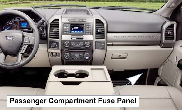
Passenger Compartment Fuse Panel:
The fuse panel is in the right-hand side of the passenger footwell behind a trim panel. To remove the trim panel, pull it toward you and swing it away from the side. To reinstall it, line up the tabs with the grooves on the panel, and then push it shut. It may be easier to access the fuse panel if you remove the finish trim piece.
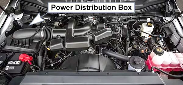
Power Distribution Box:
The power distribution box is located in the engine compartment. It has high-current fuses that protect your vehicle’s main electrical systems from overloads. If the battery has been disconnected and reconnected, some features will need to be reset.
Fuse Box Diagrams
2017
Passenger Compartment Fuse Panel
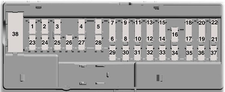
List of fuses in the passenger compartment fuse panel (2017)
| № | A | Protected Components |
|---|---|---|
| 1 | – | Not used. |
| 2 | 7.5A1 | Memory seat switch (iumbar power). |
| 3 | 20A1 | Driver door unlock relay. |
| 4 | 5A1 | Aftermarket electronic brake controller. Trailer brake controller Brake On/Off. Customer access circuits. |
| 5 | – | Not used. |
| 6 | – | Not used. |
| 7 | – | Not used. |
| 8 | – | Not used. |
| 9 | 10A2 | Brake On/Off / Pressure Switch. |
| 10 | – | Not used. |
| 11 | 5A2 | Combined sense security module. |
| 12 | 7.5A2 | Front climate control module. |
| 13 | 7.5A2 | Instrument cluster. Smart data link. Steering column control module. |
| 14 | 10A2 | Extended power restraints module. |
| 15 | 10A2 | Smart datalink connector power. |
| 16 | 15A1 | Tailgate release solenoid. |
| 17 | 5A2 | Head-up display. |
| 18 | 5A2 | Push button ignition switch. Ignition switch. Key inhibit. |
| 19 | 7.5A2 | Transmission control switch (tow/haul). Select Shift switch. |
| 20 | 7.5A2 | Active front steering module. |
| 21 | 5A2 | Head-up display. Humidity sensor. |
| 22 | 5A2 | Upfitter switch. Run/Start. PTO relays. |
| 23 | 10A1 | Accessory delay. Power Windows. Moonroof. Power folding mirrors relay. Inverter. Window/moonroof switch illumination. |
| 24 | 20A1 | Central locking system relay. |
| 25 | 30A1 | Left-hand front smart window motor. Door zone module. |
| 26 | 30A1 | Right-hand front smart window motor. Door zone module. |
| 27 | 30A1 | Moonroof. |
| 28 | 20A1 | Sony amplifier -10 channel. |
| 29 | – | Not used. |
| 30 | – | Not used. |
| 31 | 15A1 | Adjustable pedais switch. |
| 32 | 10A1 | SYNC. GPS module. Display. Radio frequency receiver. |
| 33 | 20A1 | Radio. |
| 34 | 30A1 | Run-start relay. |
| 35 | 5A1 | Extended power restraints module. |
| 36 | 15A1 | Lane keeping system. Automatic high beam control. Auto-dimming mirrors. Rear heated seats. Camera module. |
| 37 | 20A1 | Heated steering wheel. |
| 38 | 30A3 | Rear power window switch. |
| 1 Micro 2 fuse. 2 Micro 3 fuse. 3 Circuit breaker. | ||
Power Distribution Box
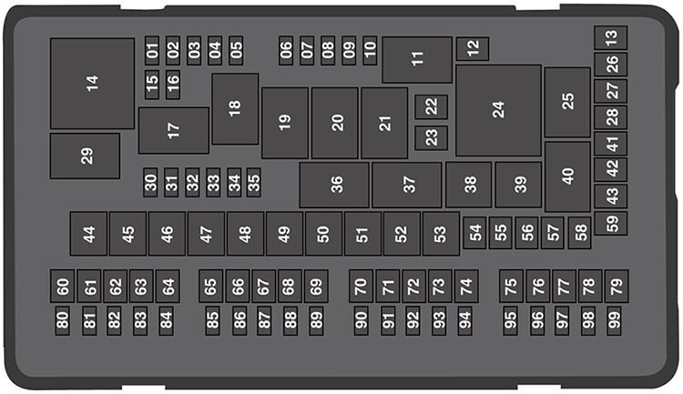
List of fuses in the power distribution box (2017)
| № | A | Protected Components |
|---|---|---|
| 1 | 20A1 | Powertrain control module. |
| 2 | 20A1 | Emissions (MIL). |
| 3 | 20A1 | Cooling fan. A/C compressor. Engine brake. |
| 4 | 20A1 | Noise suppression cap. Mass air flow sensor. Emissions. Glow plugs. Urea. |
| 5 | 15A1 | Compressed natural gas fuel control module. |
| 6 | – | Not used. |
| 7 | – | Not used. |
| 8 | – | Not used. |
| 9 | – | Not used. |
| 10 | 15A1 | Heated exterior mirrors. |
| 11 | – | CNG relay. |
| 12 | 40A2 | Heated rearwindow. |
| 13 | – | Not used. |
| 14 | – | Powertrain control module relay. |
| 15 | 20A1 | Horn. |
| 16 | 10A1 | A/C clutch relay power. |
| 17 | – | Rear heated window and heated mirrors relay. |
| 18 | – | Not used. |
| 19 | – | Not used. |
| 20 | – | Supplemental air heater bank #1 relay. |
| 21 | – | Not used. |
| 22 | 20A2 | Auxiliary power point #5 (rear console). Run-start. |
| 23 | – | Not used. |
| 24 | – | Cooling fan relay. Supplemental air heater bank #3 relay. |
| 25 | – | Glow plug module power relay. |
| 26 | – | Not used. |
| 27 | 30A2 | Trai ler tow battery charge relay. |
| 29 | – | Run-start relay. |
| 30 | 10A1 | 4×4 module. |
| 31 | 5A1 | Adaptive cruise control. Run-start. |
| 32 | 5A1 | Anti-lock brake system module. Run-start. |
| 33 | 10A1 | Powertrain control module (ISPR). Run-start. Engine control module. Transmission control module. |
| 34 | 10A1 | Blind spot information system. Run-start. Front camera. Rear camera. |
| 35 | – | Not used. |
| 36 | – | Blower motor relay. |
| 37 | – | Trai ler tow battery charge relay. |
| 38 | – | A/C compressor clutch relay. |
| 39 | – | Horn relay. |
| 40 | – | Supplemental air heater bank #2 relay. |
| 41 | 25A2 | Glow plugs. |
| 42 | 40A2 | Trailer tow lighting module. |
| 43 | 40A2 | Front blower motor. |
| 44 | 50A3 | Voltage quality module. Body control module. |
| 45 | 60 A3 | Active front steering. |
| 46 | 50A3 | Supplemental air heater bank #2. |
| 47 | 50A3 | Cooling fan. Supplemental air heater bank #3. |
| 48 | 50A3 | Body control module RP1 bus. |
| 49 | 60A3 | Inverter. |
| 50 | 50A3 | Body control module RP2 bus. |
| 51 | 60A3 | Body control module B+ feed. |
| 52 | 60A3 | Anti-lock brake system pump. |
| 53 | 50A3 | Supplemental air heater bank #1. |
| 54 | 30A3 | Trailer brake control module. |
| 55 | 30A3 | Climate controlled seat module. |
| 56 | 40A3 | Auxiliary lighting module. |
| 57 | 30A2 | Power running boards. |
| 58 | 30A2 | Compressed natural gas fuel control module relay. |
| 59 | 30A2 | Anti-lock brake system valve. |
| 60 | – | Not used. |
| 61 | 30A2 | Driver power seat. |
| 62 | 20A2 | Auxiliary power point #1 (instrument panei). |
| 63 | 30A2 | Starter motor. |
| 64 | 20A2 | Auxiliary power point #2. |
| 65 | 30A2 | Trailer tow lighting module. |
| 66 | 20A2 | Auxiliary power point #3 (center console). |
| 67 | 30A2 | Passenger power seat. |
| 68 | 20A2 | Auxiliary power point #4 (rear media bin). |
| 69 | 25A2 | 4×4 module. |
| 70 | – | Not used. |
| 71 | – | Not used. |
| 72 | 30A2 | Trailer tow left hand/right hand stop/turn. |
| 73 | – | Not used. |
| 74 | – | Not used. |
| 75 | 30A2 | Fuel pump. |
| 76 | – | Not used. |
| 77 | 30A2 | Wiper motor. |
| 78 | – | Not used. |
| 79 | 30A2 | Power sliding rear window. |
| 80 | 25A1 | 4×4 module. |
| 81 | 10A1 | 4×4 solenoid. |
| 82 | 10A1 | Power telescoping mirrors. |
| 83 | 20A1 | Rear heated seats. |
| 84 | 10A1 | Trailer tow backup lamps. |
| 85 | – | Not used. |
| 86 | – | Not used. |
| 87 | – | Not used. |
| 88 | 10A1 | Multi contour seats. |
| 89 | – | Not used. |
| 90 | 10A1 | Spot light module. |
| 91 | 10A1 | Upfitter interface module. |
| 92 | – | Not used. |
| 93 | – | Not used. |
| 94 | 15A1 | Transmission control module. |
| 95 | 10A1 | Powertrain control module keep alive power. |
| 96 | 5A1 | Rain sensor. |
| 97 | – | Not used. |
| 98 | 10A1 | Alternator sense. |
| 99 | 30A1 | Trailer tow parking lamps. |
| 1 Micro fuse. 2 M case fuse. 3 J case fuse. | ||
2018
Passenger Compartment Fuse Panel
List of fuses in the passenger compartment fuse panel (2018)
| № | A | Protected Components |
|---|---|---|
| 1 | – | Not used. |
| 2 | 7.5 A1 | Memory seat switch (lumbar power). |
| 3 | 20A1 | Driver door unlock relay. |
| 4 | 5A1 | Aftermarket electronic brake controller. Trailer brake controller Brake On/Off. Customer access circuits. |
| 5 | – | Not used. |
| 6 | – | Not used. |
| 7 | – | Not used. |
| 8 | 10A2 | Driver window switch mirror fold. |
| 9 | 10A2 | Brake On/Off / Pressure Switch. |
| 10 | – | Not used. |
| 11 | 5A2 | Combined sense security module. |
| 12 | 7.5A2 | Front climate control module. |
| 13 | 75A2 | Instrument cluster. Smart data link. Steering column control module. |
| 14 | 10A2 | Extended power restraints module. |
| 15 | 10A2 | Smart datalink connector power. |
| 16 | 15A1 | Tailgate release solenoid. |
| 17 | 5A2 | Head-up display. |
| 18 | 5A2 | Push button ignition switch. Ignition switch. Key inhibit. |
| 19 | 75A2 | Transmission control switch (tow/haul). Select Shift switch. |
| 20 | 7.5A2 | Active front steering module. |
| 21 | 5A2 | Head-up display. Humidity sensor. |
| 22 | 5A2 | Upfitter switch. Run/Start. PTO relays. |
| 23 | 10A1 | Accessory delay. Power Windows. Moonroof. Power folding mirrors relay. Inverter. Window/moonroof switch illumination. |
| 24 | 20A1 | Central locking system relay. |
| 25 | 30A1 | Left-hand front smart window motor. Door zone module. |
| 26 | 30A1 | Right-hand front smart window motor. Door zone module. |
| 27 | 30A1 | Moonroof. |
| 28 | 20A1 | Sony amplifier – 10 channel. |
| 29 | – | Not used. |
| 30 | – | Not used. |
| 31 | 15A1 | Adjustable pedais switch. |
| 32 | 10A1 | SYNC. GPS module. Display. Radio frequency receiver. |
| 33 | 20A1 | Radio. |
| 34 | 30A1 | Run-start relay. |
| 35 | 5A1 | Extended power restraints module. |
| 36 | 15A1 | Lane keeping system. Automatic high beam control. Auto-dimming mirrors. Rear heated seats. Camera module. |
| 37 | 20A1 | Heated steering wheel. |
| 38 | 30A3 | Rear power window switch. |
| 1 Micro 2 fuse. 2 Micro 3 fuse. 3 Circuit breaker. | ||
Power Distribution Box
List of fuses in the power distribution box (2018)
| № | A | Protected Components |
|---|---|---|
| 1 | 20A1 | Powertrain control module. |
| 2 | 20A1 | Emissions – malfunction indicator lamp. |
| 3 | 20A1 | Cooling fan. A/C compressor. Engine brake. |
| 4 | 20A1 | Noise suppression cap. Mass air flow sensor. Emissions. Glow plugs. Urea. |
| 5 | 15A1 | Compressed natural gas fuel control module. Fuel sensor. |
| 6 | – | Not used. |
| 7 | – | Not used. |
| 8 | – | Not used. |
| 9 | – | Not used. |
| 10 | 15A1 | Heated exterior mirrors. |
| 11 | – | Compressed natural gas relay. |
| 12 | 40A2 | Heated rearwindow. |
| 13 | – | Not used. |
| 14 | – | Powertrain control module relay. |
| 15 | 20A1 | Horn. |
| 16 | 10A1 | A/C clutch relay power. |
| 17 | – | Rear heated window and heated mirrors relay. |
| 18 | – | Trailer park lamp relay. |
| 19 | – | Not used. |
| 20 | – | Supplemental air heater bank #1 relay. |
| 21 | – | Not used. |
| 22 | – | Not used. |
| 23 | – | Not used. |
| 24 | – | Cooling fan relay. Supplemental air heater bank #3 relay. |
| 25 | – | Glow plug module power relay. |
| 26 | – | Not used. |
| 27 | 30A2 | Trai ler tow battery charge relay (if equipped). |
| 28 | – | Not used. |
| 29 | – | Run-start relay. |
| 30 | 10A1 | 4×4 module. |
| 31 | 5A1 | Adaptive cruise control. Run-start. |
| 32 | 5A1 | Anti-lock brake system module. Run-start. |
| 33 | 10A1 | Powertrain control module – ignition status power run. Run-start. Engine control module. Transmission control module. |
| 34 | 10A1 | Blind spot information system. Run-start. Front camera. Rear camera. |
| 35 | – | Not used. |
| 36 | – | Blower motor relay. |
| 37 | – | Trailer tow battery charge relay (only on non-trailer brake controller vehicles). |
| 38 | – | A/C compressor clutch relay. |
| 39 | – | Horn relay. |
| 40 | – | Supplemental air heater bank #2 relay. |
| 41 | 25A2 | Glow plugs. |
| 42 | 40A2 | Trailer tow lighting module (if equipped). |
| 43 | 40A2 | Front blower motor. |
| 44 | 50A3 | Voltage quality. Body control module power. |
| 45 | 60A3 | Active front steering. |
| 46 | 50A3 | Supplemental air heater bank #2. |
| 47 | 50A3 | Cooling fan. Supplemental air heater bank #3. |
| 48 | 50A3 | Body control module run power 1 bus. |
| 49 | 60A3 | Inverter. |
| 50 | 50A3 | Body control module run power 2 bus. |
| 51 | 60A3 | Body control module B+ feed. |
| 52 | 60A3 | Anti-lock brake system pump. |
| 53 | 50A3 | Supplemental air heater bank #1. |
| 54 | 30A3 | Trailer brake control module. |
| 55 | 30A3 | Climate controlled seat module. |
| 56 | 40A3 | Auxiliary lighting module. |
| 57 | 30 A2 | Power running boards. |
| 58 | 30 A2 | Compressed natural gas fuel control module relay. |
| 59 | 30A2 | Anti-lock brake system valve. |
| 60 | – | Not used. |
| 61 | 30A2 | Driver power seat. |
| 62 | 20A2 | Auxiliary power point #1 (instrument panei). |
| 63 | 30A2 | Starter motor. |
| 64 | 20A2 | Auxiliary power point #2. |
| 65 | 30A2 | Trailer tow lighting module (if equipped). |
| 66 | 20A2 | Auxiliary power point #3 (center console). |
| 67 | 30A2 | Passenger power seat. |
| 68 | 20A2 | Auxiliary power point #4 (USB charger, rear center console). |
| 69 | 25A2 | 4×4 module. |
| 70 | 20A2 | Auxiliary power point #5 (rear center console). |
| 71 | – | Not used. |
| 72 | 30A2 | Trailer tow left hand/right hand stop/turn (if equipped, not present with trailer brake controller). |
| 73 | – | Not used. |
| 74 | – | Not used. |
| 75 | 30A2 | Fuel pump. |
| 76 | – | Not used. |
| 77 | 30A2 | Wiper motor. |
| 78 | – | Not used. |
| 79 | 30A2 | Power sliding rear window. |
| 80 | 25A2 | 4×4 module. |
| 81 | 10A1 | 4×4 solenoid. |
| 82 | 10A1 | Power telescoping mirrors. |
| 83 | 20A1 | Rear heated seats. |
| 84 | 10A1 | Trailer tow backup lamps (if equipped). |
| 85 | – | Not used. |
| 85 | – | Not used. |
| 87 | – | Not used. |
| 88 | 10A1 | Multi contour seats. |
| 89 | – | Not used. |
| 90 | 10A1 | Spot light module. |
| 91 | 10A1 | Upfitter interface module. |
| 92 | – | Not used. |
| 93 | – | Not used. |
| 94 | 15A1 | Transmission control module. |
| 95 | 10A1 | Powertrain control module keep alive power. |
| 96 | 5A1 | Rain sensor. |
| 97 | 10A1 | Run/Start control for Auxiliary power point #5 |
| 98 | 10A1 | Alternator sense. |
| 99 | 30A1 | Trailer tow parking lamps. |
| 1 Micro fuse. 2 M case fuse. 3 J case fuse. | ||
2019
Passenger Compartment Fuse Panel
List of fuses in the passenger compartment fuse panel (2019)
| № | A | Protected Component |
|---|---|---|
| 1 | – | Not used. |
| 2 | 7.5A1 | Memory seat switch (lumbar power). |
| 3 | 20A1 | Driver door unlock relay. |
| 4 | 5A1 | Aftermarket electronic brake controller. Trailer brake controller Brake On/Off. Customer access circuits. |
| 5 | – | Not used. |
| 6 | – | Not used. |
| 7 | – | Not used. |
| 8 | 10A2 | Driver window switch mirror fold. |
| 9 | 10A2 | Brake On/Off / Pressure Switch. |
| 10 | 5A1 | Embedded Modem. |
| 11 | 5A2 | Combined sense security module. |
| 12 | 7.5A2 | Front climate control module. |
| 13 | 7.5A2 | Instrument cluster. Smart data link. Steering column control module. |
| 14 | 10A2 | Extended power restraints module. |
| 15 | 10A2 | Smart datalink connector power. |
| 16 | 15A1 | Tailgate release solenoid. |
| 17 | 5A2 | Head-up display. |
| 18 | 5A2 | Push button ignition switch. Ignition switch. Key inhibit. |
| 19 | 7.5A2 | Transmission control switch (tow/haul). Select Shift switch. |
| 20 | 7.5A2 | Active front steering module. |
| 21 | 5A2 | Head-up display. Humidity sensor. |
| 22 | 5A2 | Upfitter switch. Run/Start. PTO relays. |
| 23 | 10A1 | Accessory delay. Power Windows. Moonroof. Power folding mirro rs relay. Inverter. Window/moonroof switch illumination. |
| 24 | 20A1 | Central locking system relay. |
| 25 | 30A1 | Left-hand front smart window motor. Door zone module. |
| 25 | 30A1 | Right-hand front smart window motor. Door zone module. |
| 27 | 30A1 | Moonroof. |
| 28 | – | Not used. |
| 29 | 30A1 | Bang & Olufsen Amplifier. |
| 30 | – | Not used. |
| 31 | 15A1 | Adjustable pedais switch. |
| 32 | 10A1 | SYNC. GPS module. Display. Radio frequency receiver. |
| 33 | 20A1 | Radio. |
| 34 | 30A1 | Run-start relay. |
| 35 | 5A1 | Extended power restraints module. |
| 36 | 15A1 | Lane keeping system. Automatic high beam control. Auto-dimming mirrors. Rear heated seats. Camera module. |
| 37 | 20A1 | Heated steering wheel. |
| 38 | 30A3 | Rear power window switch. |
| 1 Micro 2 fuse. 2 Micro 3 fuse. 3 Circuit breaker. | ||
Power Distribution Box
List of fuses in the power distribution box (2019)
| № | A | Protected Component |
|---|---|---|
| 1 | 20A1 | Powertrain control module. |
| 2 | 20A1 | Emissions – malfunction indicator lamp. |
| 3 | 20A1 | Cooling fan. A/C compressor. Engine brake. |
| 4 | 20A1 | Noise suppression cap. Mass air flow sensor. Emissions. Glow plugs. Urea. |
| 5 | 15A1 | Compressed natural gas fuel control module. Fuel sensor. |
| 6 | – | Not used. |
| 7 | – | Not used. |
| 8 | – | Not used. |
| 9 | – | Not used. |
| 10 | 15A1 | Heated exterior mirrors. |
| 11 | – | Compressed natural gas relay. |
| 12 | 40A2 | Heated rear window. |
| 13 | – | Not used. |
| 14 | – | Powertrain control module relay. |
| 15 | 20A1 | Horn. |
| 16 | 10A1 | A/C clutch relay power. |
| 17 | – | Rear heated window and heated mirrors relay. |
| 18 | – | Trailer park lamp relay. |
| 19 | – | Not used. |
| 20 | – | Supplemental air heater bank #1 relay. |
| 21 | – | Not used. |
| 22 | – | Not used. |
| 23 | – | Not used. |
| 24 | – | Cooling fan relay. Supplemental air heater bank #3 relay. |
| 25 | – | Glow plug module power relay. |
| 25 | – | Not used. |
| 27 | 30A2 | Trailer tow battery charge relay (if equipped). |
| 28 | – | Not used. |
| 29 | – | Run-start relay. |
| 30 | 10A1 | 4×4 module. |
| 31 | 5A1 | Adaptive cruise control. Run-start. |
| 32 | 5A1 | Anti-lock brake system module. Run-start. |
| 33 | 10A1 | Powertrain control module – ignition status power run. Run-start. Engine control module. Transmission control module. |
| 34 | 10A1 | Blind spot information system. Run-start. Front camera. Rear camera. |
| 35 | – | Not used. |
| 36 | – | Blower motor relay. |
| 37 | – | Trailer tow battery charge relay (only on non-trailer brake controller vehicles). |
| 38 | – | A/C compressor clutch relay. |
| 39 | – | Horn relay. |
| 40 | – | Supplemental air heater bank #2 relay. |
| 41 | 25A2 | Glow plugs. |
| 42 | 40A2 | Trailer tow lighting module (if equipped). |
| 43 | 40A2 | Front blower motor. |
| 44 | 50A3 | Voltage quality. Body control module power. |
| 45 | 60A3 | Active front steering. |
| 46 | 50A3 | Supplemental air heater bank #2. |
| 47 | 50A3 | Cooling fan. Supplemental air heater bank #3. |
| 48 | 50A3 | Body control module run power 1 bus. |
| 49 | 60A3 | Inverter. |
| 50 | 50A3 | Body control module run power 2 bus. |
| 51 | 60A3 | Body control module B+ feed. |
| 52 | 60A3 | Anti-lock brake system pump. |
| 53 | 50A3 | Supplemental air heater bank #1. |
| 54 | 30A3 | Trailer brake control module. |
| 55 | 30A3 | Climate controlled seat module. |
| 56 | 40A3 | Auxiliary lighting module. |
| 57 | 30A2 | Power running boards. |
| 58 | 30A2 | Compressed natural gas fuel control module relay. |
| 59 | 30A2 | Anti-lock brake system valve. |
| 60 | – | Not used. |
| 61 | 30A2 | Driver power seat. |
| 62 | 20A2 | Auxiliary power point #1 (instrument panei). |
| 63 | 30A2 | Starter motor. |
| 64 | 20A2 | Auxiliary power point #2. |
| 65 | 30A2 | Trailer tow lighting module (if equipped). |
| 66 | 20A2 | Auxiliary power point #3 (center console). |
| 67 | 30A2 | Passenger power seat. |
| 68 | 20A2 | Auxiliary power point #4 (USB charger, rear center console). |
| 69 | 25A2 | 4×4 module. |
| 70 | 20A2 | Auxiliary power point #5 (rear center console). |
| 71 | – | Not used. |
| 72 | 30A2 | Trailer tow left hand/right hand stop/turn (if equipped, not present with trailer brake controller). |
| 73 | – | Not used. |
| 74 | – | Not used. |
| 75 | 30A2 | Fuel pump. |
| 76 | – | Not used. |
| 77 | 30A2 | Wiper motor. |
| 78 | – | Not used. |
| 79 | 30A2 | Power sliding rear window. |
| 80 | 25A1 | 4×4 module. |
| 81 | 10A1 | 4×4 solenoid. |
| 82 | 10A1 | Power telescoping mirrors. |
| 83 | 20A1 | Rear heated seats. |
| 84 | 10A1 | Trailer tow backup lamps (if equipped). |
| 85 | – | Not used. |
| 86 | – | Not used. |
| 87 | – | Not used. |
| 88 | 10A1 | Multi contour seats. |
| 89 | – | Not used. |
| 90 | 10A1 | Spot light module. |
| 91 | 10A1 | Upfitter interface module. |
| 92 | – | Not used. |
| 93 | – | Not used. |
| 94 | 15A1 | Transmission control module. |
| 95 | 10A1 | Powertrain control module keep alive power. |
| 96 | 5A1 | Rain sensor. |
| 97 | 10A1 | Run/Start control for Auxiliary power point #5 |
| 98 | 10A1 | Alternator sense. |
| 99 | 30A1 | Trailer tow parking lamps. |
| 1 Micro fuse. 2 M case fuse. 3 J case fuse. | ||
Conclusion
Understanding the fuse box and relay locations on your 2017–2019 Ford F-250, F-350, F-450, or F-550 makes it much easier to handle common electrical issues without unnecessary guesswork. From the engine bay’s power distribution box to the cabin’s fuse panel and optional auxiliary relay box, knowing where to look and how to safely access each one, puts routine troubleshooting well within reach.
Always double-check amperage ratings, use the printed fuse diagram for accurate identification, and handle relays and fuses with care. If you’ve replaced a fuse and the problem continues, or if you’re dealing with a more complex electrical fault involving the Smart Junction Box, it’s best to consult a certified Ford technician to avoid further complications.