Learn about Ford F-250 (1997) fuse box and relay’s locations, functions, and maintenance tips for optimal vehicle electrical system.
The 1997 Ford F-250 represents the final year of the classic “OBS” (Old Body Style) generation before Ford introduced the redesigned Super Duty platform in 1999. This truck uses a simpler, more traditional electrical system compared to modern vehicles, but fuses and relays remain essential for protecting your truck’s wiring from electrical faults and overloads.
If you’re experiencing issues like a dead radio, malfunctioning dashboard lights, or wipers that won’t turn on, a blown fuse or faulty relay is often the cause. Knowing exactly where to find your 1997 F-250’s fuse box and relays can help you diagnose these problems quickly without unnecessary guesswork or an unplanned trip to the shop.
This guide walks through the fuse box location, relay placement, and safe access methods specific to the 1997 Ford F-250.
MUST READ: DYI – How to Check Car Fuses?
(1997) Ford F-250 fuse box and relay with Diagram
WARNING
- Never replace a fuse with one that has a higher amperage rating.
- A fuse with a too-high amperage could damage the electrical part and cause a fire.
- On no account should fuses be repaired (e.g. patched up with tin foil or wire) as this may cause serious damage elsewhere in the electrical circuit or cause a fire.
- If a fuse blows repeatedly, do not keep replacing it. Instead, have the cause for the repeated short circuit or overload tracked and fixed.
- Terminal and harness assignments for individual connectors will vary depending on vehicle equipment level, model, and market.
Ford F-250 (1997) fuse assignment
Ford F-250 Year of production: 1997

Where Is the Fuse Box Located on the 1997 Ford F-250?
The 1997 F-250 uses a straightforward electrical layout consisting of one main interior fuse panel and several individual relays mounted throughout the engine bay, rather than a centralized power distribution box.
1. Interior Fuse Panel (Under the Dashboard)
The primary fuse box is located under the dashboard on the driver’s side, positioned above the pedals and to the left of the steering column.
How to access it:
- Sit in the driver’s seat and look beneath the dash near the kick panel.
- The fuse panel is typically covered by a flip-down door or a flat plastic panel secured with one or two screws.
- Open or remove the cover to expose the fuse block.
This panel controls circuits such as interior lighting, the radio, turn signals, gauge cluster, heater/blower motor, and wipers. Since this is the fuse box you’ll likely check most often, it’s helpful to familiarize yourself with its layout before you actually need it.
2. Engine Bay Relays
Instead of grouping relays into one labeled box, the 1997 F-250 mounts individual relays directly in the engine compartment, typically near the firewall, fender wells, or battery.
Common relay locations include:
- Horn relay – usually mounted near the firewall on the driver’s side.
- Starter relay – typically located on the inner fender or near the battery.
- Blower motor relay – often found near the heater box on the firewall.
- Headlight relay (if equipped) – generally positioned near the battery or front of the engine bay.
How to access them:
- Open the hood and visually inspect the areas near the firewall and battery.
- Relays are small, black, square or rectangular components plugged into the wiring harness, no cover removal is necessary, though some may be tucked behind brackets or other components.
- To remove a relay, gently pull it straight up or rock it slightly side to side to release it from its socket.
Because these relays aren’t consolidated into a single labeled box, a factory service manual or wiring diagram is especially useful for confirming exact locations, as placement can vary slightly depending on engine type (gas V8 or Power Stroke diesel).
3. In-Line Fuses
Certain circuits, particularly aftermarket accessories or specific lighting circuits, may use in-line fuse holders spliced directly into the wiring harness rather than housed in the main fuse panel. These are commonly found behind the dashboard, near the firewall, or along the engine bay wiring harness.
If a component isn’t protected by the main fuse panel and doesn’t appear to have a dedicated relay, check along the wiring harness for a small in-line fuse holder.
How to Identify the Right Fuse or Relay
The fuse panel cover typically includes a printed legend listing fuse amperage ratings and the circuits they protect. Since labeling on these older trucks is often brief, it may list general categories like “Gauges,” “Radio,” or “Turn Signal” rather than specific component names.
When troubleshooting:
- Match the malfunctioning component to the closest labeled circuit on the fuse panel.
- Use a test light or multimeter to confirm which fuse has blown if the panel labeling is faded or unclear.
- For relays, cross-reference their location and function using a wiring diagram specific to your engine type, since layout can differ slightly between gas and diesel models.
Safety Precautions Before Checking Fuses or Relays
- Turn off the ignition and remove the key before touching any fuse or relay.
- For more involved diagnostics, disconnect the negative battery terminal, especially when working near the starter relay or battery.
- Use a fuse puller or needle-nose pliers to remove fuses, avoid metal screwdrivers, which can cause sparking.
- Always replace a fuse with one of the same amperage rating. Installing a higher-rated fuse can damage wiring or create a fire hazard.
- If a newly installed fuse blows immediately, stop and inspect the circuit for a short rather than continuing to swap fuses.
- Given the age of this truck, inspect wiring and relay connectors for corrosion or brittle insulation, which is common after decades of use
Checking and Replacing Fuses in Ford F-250
If electrical components in the vehicle are not working, a fuse may have blown. Blown fuses are identified by a broken element. Check the appropriate fuses before replacing any electrical components. Even after a fuse is replaced, it may continue to blow if the cause of the overload is not identified and corrected. If a fuse continues to blow, have the vehicle’s electrical system checked.
Location of Fuse Boxes
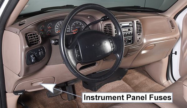
Instrument Panel Fuses:
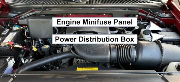
Engine Minifuse Panel: The minifuse panel is located behind the power distribution box.
Power Distribution Box: Lift cover towards left of vehicle to access the power distribution box.
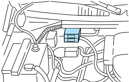
Primary Battery Fuses (Megafuses):
Primary battery fuses are located under the PRIMARY BATTERY FUSE cover next to starter relay. Ford recommends that megafuses only be serviced by a qualified service technician.
Fuse Box Diagrams
1997
Instrument Panel Fuses
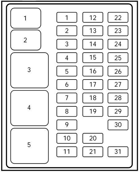
List of fuses in the Instrument panel fuses (1997)
| № | A | Description |
|---|---|---|
| 1 | 15A | Stop/turn lamps and turn indicators |
| 2 | 5A | Instrument cluster |
| 3 | 25A | Cigarette lighter |
| 4 | 5A | Power mirrors, autolamp, remote anti-theft / keyless entry, headlamp relay and parking lamp relay |
| 5 | 15A | Speed control, daytime running lamps, climate control blend door, backup lamps, A/C clutch coil |
| 6 | 5A | Brake-shift interlock, generic electronic module (GEM) / central timer module (CTM) and air suspension module |
| 7 | – | Not used |
| 8 | 5A | Radio, remote anti-theft / keyless entry, GEM module/CTM module |
| 9 | – | Not used |
| 10 | – | Not used |
| 11 | 30A | Wiper system |
| 12 | 5A | On-board diagnostic (OBD II) data link connector |
| 13 | 15A | Brake ON/OFF switch, rear anti-lock brake module and brake pressure switch |
| 14 | 15A | Interior lamps and accessory delay relay |
| 15 | 5A | GEM module/CTM module |
| 16 | 20A | High beam headlamps |
| 17 | – | Not used |
| 18 | 5A | Instrument illumination |
| 19 | 10A | Air bag diagnostic monitor, instrument cluster |
| 20 | 5A | GEM module/CTM module and powertrain control module (PCM) |
| 21 | 15A | Starter relay |
| 22 | 10A | Air bag diagnostic monitor and passenger air bag deactivate switch |
| 23 | 10A | 4WD clutch relay, electronic flasher, 4WD/2WD vacuum solenoids and trailer tow battery charge relay |
| 24 | 10A | l/P blower relay |
| 25 | 5A | 4WABS module and relay |
| 26 | 10A | Right low beam headlamp and DRL module |
| 27 | 5A | Foglamp relay |
| 28 | 10A | Left low beam headlamp |
| 29 | 5A | Autolamp, instrument cluster, transmission control indicator lamp and switch |
| 30 | 30A | Ignition coils and PCM relay |
| 31 | – | Not used |
| Relays | ||
| 1 | Interior lamps relay | |
| 2 | Battery saver relay | |
| 3 | Not used | |
| 4 | One touch down relay | |
| 5 | Accessory delay relay | |
Power Distribution Box
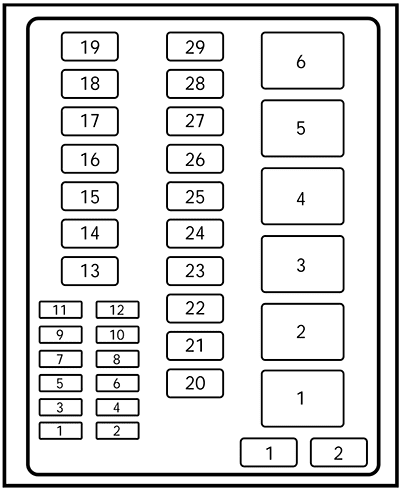
List of fuses in the power distribution box (1997)
| № | A | Description |
|---|---|---|
| 1 | 20A | Trailer tow back-up and tail lamps |
| 2 | 10A | Air bag diagnostic monitor |
| 3 | 15A | Power locks |
| 4 | 15A | Air suspension |
| 5 | 20A | Horn |
| 6 | 15A | Audio system |
| 7 | 15A | Parking and tail lamps |
| 8 | 30A | Headlamps |
| 9 | 15A | Daytime running lamps and fog lamps |
| 10 | 25A | Auxiliary power point |
| 11 | – | Not used |
| 12 | – | Not used |
| 13 | – | Not used |
| 14 | 60A/20A | 4W ABS/rear anti-lock brake |
| 15 | 50A | Air suspension compressor |
| 16 | 40A | Trailer tow battery charge and stop/turn lamps |
| 17 | 30A | 4WD transfer case shift motor and clutch |
| 18 | 30A | Driver power seat |
| 19 | 20A | Fuel pump |
| 20 | 50A | Instrument panel fuse panei ignition switch feed |
| 21 | 50A | Instrument panel fuse panei ignition switch feed |
| 22 | 50A | l/P fuse panei battery feed |
| 23 | 40A | l/P blower |
| 24 | 30A | PCM power |
| 25 | 30A | Power Windows |
| 26 | – | Not used |
| 27 | – | Not used |
| 28 | 30A | Trailer tow electronic brake |
| 29 | – | Not used |
| Diodes | ||
| 1 | Rear ABS diode | |
| 2 | PCM diode | |
| Relays | ||
| 1 | Windshield wipers HI/LO speed | |
| 2 | Windshield wipers run/park relay | |
| 3 | Washer pump relay | |
| 4 | Fuel pump relay | |
| 5 | Horn relay | |
| 6 | PCM power relay | |
Engine Minifuse Panel
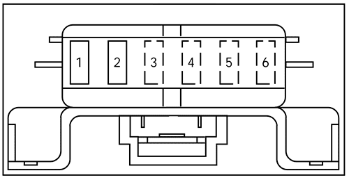
List of fuses in the engine minifuse panel (1997)
| № | A | Description |
|---|---|---|
| 1 | 5A | Powertrain control module (PCM) |
| 2 | 20A | Trailer tow stop / turn lamps |
| 3 | – | Not used |
| 4 | – | Not used |
| 5 | – | Not used |
| 6 | – | Not used |
Primary Battery Fuses (Megafuses)
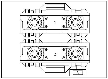
List of fuses in the Primary battery fuses (megafuses) (1997)
| № | A | Description |
|---|---|---|
| 1 | 175A | Power network box megafuse |
| 2 | 175A | Alternator megafuse |
| 3 | 20A | Alternator field minifuse |
Conclusion
The 1997 Ford F-250 uses a simple, no-frills electrical system with one main interior fuse panel and several individually mounted engine bay relays. While this layout lacks the centralized fuse boxes found in later Super Duty trucks, it’s relatively easy to diagnose once you know where each component is located.
Always handle fuses and relays carefully, confirm amperage ratings before replacing anything, and reference a factory wiring diagram when relay locations aren’t immediately obvious. If electrical issues persist after checking your fuses and relays, or if you notice significant wiring wear and corrosion, consulting a mechanic experienced with older Ford trucks is a smart next step.