Learn about Dodge Challenger 2008-2014 fuse box and relay’s locations, functions, and maintenance tips for optimal vehicle electrical system.
The Dodge Challenger (2008-2014) revives the classic American muscle car with a retro-inspired design. It is available in several body styles, including the base SE, the performance-focused R/T, and the high-powered SRT8. Each variant offers distinct features such as different engine options, ranging from a 3.5L V6 to a 6.4L HEMI V8, providing a variety of power outputs. The aggressive exterior is complemented by a spacious, driver-focused interior with advanced infotainment and comfort features.
In terms of the electrical system, the Dodge Challenger has a fuse box and relays that manage critical electrical functions, such as the lighting system, engine control, and audio system. The fuse box, located in the engine compartment, protects circuits from overloads. Relays, situated near the fuse box, help manage high-current devices like the fuel pump and cooling fans. Regular inspection of fuses and relays is essential to avoid electrical malfunctions, which can affect the car’s performance or even lead to complete power failure.
MUST READ: DYI – How to Check Car Fuses?
(2008-2014) Dodge Challenger fuse box and relay with Diagram
WARNING
- Never replace a fuse with one that has a higher amperage rating.
- A fuse with a too-high amperage could damage the electrical part and cause a fire.
- On no account should fuses be repaired (e.g. patched up with tin foil or wire) as this may cause serious damage elsewhere in the electrical circuit or cause a fire.
- If a fuse blows repeatedly, do not keep replacing it. Instead, have the cause for the repeated short circuit or overload tracked and fixed.
- Terminal and harness assignments for individual connectors will vary depending on vehicle equipment level, model, and market.
Dodge Challenger 2008-2014 fuse assignment
Year of production: from 2008, 2009, 2010, 2011, 2012, 2013, 2014
Location of Fuse Boxes
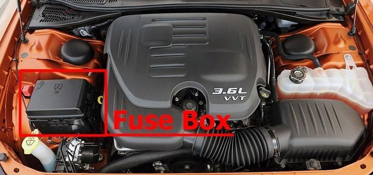
Integrated Power Module:
The Integrated Power Module (IPM) is located in the engine compartment. This module contains fuses and relays.
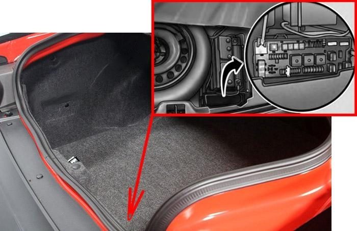
Rear Power Distribution Center:
There is also a power distribution center located in the trunk under the spare tire access panel. This center contains fuses and relays.
Fuse Box Diagrams
2008
Integrated Power Module
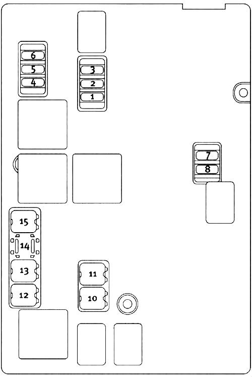
List of fuses in the IPM (2008)
| № | Cartridge Fuse | Mini-Fuse | Description |
|---|---|---|---|
| 1 | – | 15A Blue | Washer Motor |
| 2 | – | 25A Neutral | Powertrain Control Module (PCM) |
| 3 | – | 25A Neutral | Ignition Run/Start |
| 4 | – | 25A Neutral | EGR Solenoid / Alternator |
| 5 | – | – | – |
| 6 | – | 25A Neutral | Ignition Coils / Injectors |
| 7 | – | – | – |
| 8 | – | 25A Neutral | Starter |
| 9 | – | – | – |
| 10 | 30A Pink | – | Windshield Wiper |
| 11 | 30A Pink | – | Anti-Lock Brake System (ABS) Valves |
| 12 | 40A Green | – | Radiator Fan Lo/High |
| 13 | 50A Red | – | Anti-Lock Brake System (ABS) Pump Motor |
| 14 | – | – | – |
| 15 | 50A Red | – | Radiator Fan |
Rear Power Distribution Center
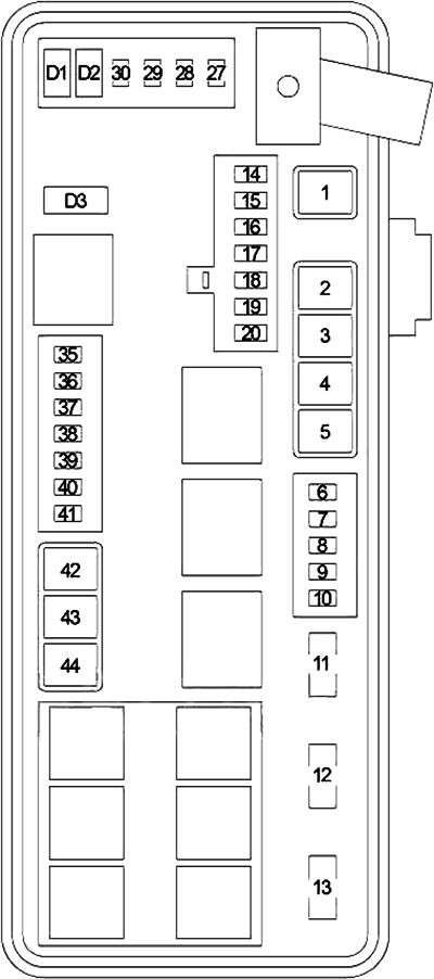
List of fuses in the Rear PDC (2008)
| № | Cartridge Fuse | Mini-Fuse | Description |
|---|---|---|---|
| 1 | 60A Yellow | – | Ignition Off Draw (IOD) |
| 2 | 40A Green | – | Integrated Power Module (IPM) |
| 3 | – | – | – |
| 4 | 40A Green | – | Integrated Power Module (IPM) |
| 5 | 30A Pink | – | Heated Seats – if equipped |
| 6 | – | 20A Yellow | Fuel Pump |
| 7 | – | 20A Yellow | Sub Amp – if equipped |
| 8 | – | 15A Blue | Diagnostic Link Connector (DLC) / Wireless Control Module (WCM) / Wireless Ignition Node (WIN) |
| 9 | – | 20A Yellow | Power Outlet |
| 10 | – | – | – |
| 11 | 25A circuit breaker | Cluster / Driver Seat Switch | |
| 12 | 25A circuit breaker | Passenger Seat Switch | |
| 13 | 25A circuit breaker | Door Modules / Driver Power Window Switch / Passenger Power Window | |
| 14 | – | 10A Red | AC Heater Control / Cluster / Security Module – if equipped |
| 15 | – | – | – |
| 16 | – | – | – |
| 17 | – | 20A Yellow | Cluster |
| 18 | – | 20A Yellow | Selectable Power Outlet |
| 19 | – | 10A Red | Stop Lights |
| 20 | – | – | – |
| 21 | – | – | – |
| 22 | – | – | – |
| 23 | – | – | – |
| 24 | – | – | – |
| 25 | – | – | – |
| 26 | – | – | – |
| 27 | – | 10A Red | Occupant Restraint Controller (ORC) |
| 28 | – | 10A Red | Ignition Run |
| 29 | – | 5A Orange | Cluster / Electronic Stability Program (ESP) / Powertrain Control Module (PCM) / STOP LIGHT Switch |
| 30 | – | 10A Red | Door Modules / Power Mirrors / Steering Control Module (SCM) |
| 31 | – | – | – |
| 32 | – | – | – |
| 33 | – | – | – |
| 34 | – | – | – |
| 35 | – | 5A Orange | Antenna Module – if equipped / Power Mirrors |
| 36 | – | 20A Yellow | Hands-Free Phone – if equipped / /Radio |
| 37 | – | 15A Blue | Transmission |
| 38 | – | 10A Red | Cargo Light / Vehicle Information Module – if equipped |
| 39 | – | 10A Red | Heated Mirrors – if equipped |
| 40 | – | 5A Orange | Auto Inside Rearview Mirror / Heated Seats – if equipped / Switch Bank |
| 41 | – | 10A Red | AC Heater Control / Headlights / Tire Pressure Monitoring – if equipped |
| 42 | 30A Pink | – | Front Blower Motor |
| 43 | 30A Pink | – | Rear Window Defroster |
| 44 | 20A Blue | – | Amplifier – if equipped / Sunroof – if equipped |
2009
Integrated Power Module
List of fuses in the IPM (2009)
| № | Cartridge Fuse | Mini-Fuse | Description |
|---|---|---|---|
| 1 | – | 15A Blue | Washer Motor |
| 2 | – | 25A Neutral | Powertrain Control Module (PCM) |
| 3 | – | 25A Neutral | Ignition Run /Start |
| 4 | – | 25A Neutral | EGR Solenoid / Alternator |
| 5 | – | – | – |
| 6 | – | 25A Neutral | Ignition Coils / Injectors |
| 7 | – | – | – |
| 8 | – | 30A Green | Starter |
| 9 | – | – | – |
| 10 | 30A Pink | – | Windshield Wiper |
| 11 | 30A Pink | – | Anti-Lock Brake System (ABS) Valves |
| 12 | 40A Green | – | Radiator Fan Lo/High |
| 13 | 50A Red | – | Anti-Lock Brake System (ABS) Pump Motor |
| 14 | – | – | – |
| 15 | 50A Red | – | Radiator Fan |
Rear Power Distribution Center
List of fuses in the Rear PDC (2009)
| № | Cartridge Fuse | Mini-Fuse | Description |
|---|---|---|---|
| 1 | 60A Yellow | – | Ignition Off Draw (IOD) Cavity 1 of the Rear Power Distribution Center contains a black IOD fuse needed for vehicle processing during assembly. The service replacement part is a 60 Amp yellow cartridge fuse. |
| 2 | 40A Green | – | Integrated Power Module (IPM) |
| 3 | – | – | – |
| 4 | 40A Green | – | Integrated Power Module (IPM) |
| 5 | 30A Pink | – | Pleated Seats – if equipped |
| 6 | – | 20A Yellow | Fuel Pump |
| 7 | – | 15A Blue | Sub Amp – if equipped |
| 8 | – | 15A Blue | Diagnostic Link Connector (DLC) / Wireless Control Module (WCM) / Wireless Ignition Node (WIN) |
| 9 | – | 20A Yellow | Power Outlet |
| 10 | – | – | – |
| 11 | 25A circuit breaker | Cluster / Driver Seat Switch | |
| 12 | 25A circuit breaker | Passenger Seat Switch | |
| 13 | 25A circuit breaker | Door Modules / Driver Power Window Switch / Passenger Power Window | |
| 14 | – | 10A Red | AC Heater Control / Cluster / Security Module – if equipped |
| 15 | – | – | – |
| 16 | – | – | – |
| 17 | – | 20A Yellow | Cluster |
| 18 | – | 20A Yellow | Selectable Power Outlet |
| 19 | – | 10A Red | Stop Lights |
| 20 | – | – | – |
| 21 | – | – | – |
| 22 | – | – | – |
| 23 | – | – | – |
| 24 | – | – | – |
| 25 | – | – | – |
| 26 | – | – | – |
| 27 | – | 10A Red | Occupant Restraint Controller (ORC) |
| 28 | – | 10A Red | Ignition Run |
| 29 | – | 5A Orange | Cluster / Electronic Stability Program (ESP) / Powertrain Control Module (PCM) / STOP LIGHT Switch |
| 30 | – | 10A Red | Door Modules / Power Mirrors / Steering Control Module (SCM) |
| 31 | – | – | – |
| 32 | – | – | – |
| 33 | – | – | – |
| 34 | – | – | – |
| 35 | – | 5A Orange | Antenna Module – if equipped / Power Mirrors |
| 36 | – | 25A Clear | Hands-Free Phone – if equipped / Radio / Amplifier Feed |
| 37 | – | 15A Blue | Transmission |
| 38 | – | 10A Red | Cargo Light / Vehicle Information Module – if equipped |
| 39 | – | 10A Red | Heated Mirrors – if equipped |
| 40 | – | 5A Orange | Auto Inside Rearview Mirror / Heated Seats – if equipped / Switch Bank |
| 41 | – | – | – |
| 42 | 30A Pink | – | Front Blower Motor |
| 43 | 30A Pink | – | Rear Window Defroster |
| 44 | 20A Blue | – | Amplifier / Sunroof – if equipped |
2010
Integrated Power Module
List of fuses in the IPM (2010)
| № | Cartridge Fuse | Mini-Fuse | Description |
|---|---|---|---|
| 1 | – | 15A Blue | Washer Motor |
| 2 | – | 25A Natural | Powertrain Control Module (PCM) |
| 3 | – | 25A Natural | Ignition Run/Start |
| 4 | – | 25A Natural | EGR Solenoid / Alternator |
| 5 | – | – | – |
| 6 | – | 25A Natural | Ignition Coils / Injectors |
| 7 | – | 25A Natural | Headlamp Washer Relay – If Equipped |
| 8 | – | 30A Green | Starter |
| 9 | – | – | – |
| 10 | 30A Pink | – | Windshield Wiper |
| 11 | 30A Pink | – | Anti-Lock Brake System (ABS) Valves |
| 12 | 40A Green | – | Radiator Fan Lo/High |
| 13 | 50A Red | – | Anti-Lock Brake System (ABS) Pump Motor |
| 14 | – | – | – |
| 15 | 50A Red | – | Radiator Fan |
Rear Power Distribution Center
List of fuses in the Rear PDC (2010)
| № | Cartridge Fuse | Mini-Fuse | Description |
|---|---|---|---|
| 1 | 60A Yellow | – | Ignition Off Draw (IOD) Cavity 1 of the Rear Power Distribution Center contains a black IOD fuse needed for vehicle processing during assembly. The service replacement part is a 60 Amp yellow cartridge fuse. |
| 2 | 40A Green | – | Integrated Power Module (IPM) |
| 3 | – | – | – |
| 4 | 40A Green | – | Integrated Power Module (IPM) |
| 5 | 30A Pink | – | Heated Seats – If Equipped |
| 6 | – | 20A Yellow | Fuel Pump |
| 7 | – | 15A Blue | Sub Amp – If Equipped |
| 8 | – | 15A Blue | Diagnostic Link Connector (DLC) / Wireless Control Module (WCM) / Wireless Ignition Node (WIN) |
| 9 | – | 20A Yellow | Power Outlet |
| 10 | – | – | – |
| 11 | 25A circuit breaker | Cluster / Driver Seat Switch | |
| 12 | 25A circuit breaker | Passenger Seat Switch | |
| 13 | 25A circuit breaker | Door Modules / Driver Power Window Switch / Passenger Power Window | |
| 14 | – | 10A Red | AC Heater Control / Cluster / Security Module – If Equipped |
| 15 | – | – | – |
| 16 | – | – | – |
| 17 | – | 20A Yellow | Cluster |
| 18 | – | 20A Yellow | Selectable Power Outlet |
| 19 | – | 10A Red | Stop Lights |
| 20 | – | – | – |
| 21 | – | – | – |
| 22 | – | – | – |
| 23 | – | – | – |
| 24 | – | – | – |
| 25 | – | – | – |
| 26 | – | – | – |
| 27 | – | 10A Red | Occupant Restraint Controller (ORC) |
| 28 | – | 10A Red | Ignition Run, AC Heater Control / Occupant Restraint Controller (ORC) |
| 29 | – | 5A Orange | Cluster / Electronic Stability Program (ESP) / Powertrain Control Module (PCM) / STOP LIGHT Switch |
| 30 | – | 10A Red | Door Modules / Power Mirrors / Steering Control Module (SCM) |
| 31 | – | – | – |
| 32 | – | – | – |
| 33 | – | – | – |
| 34 | – | – | – |
| 35 | – | 5A Orange | Antenna Module – If Equipped / Power Mirrors |
| 36 | – | 25A Natural | Hands-Free Phone – If Equipped / Radio / Amplifier Feed |
| 37 | – | 15A Blue | Transmission |
| 38 | – | 10A Red | Cargo Light / Vehicle Information Module – If Equipped |
| 39 | – | 10A Red | Heated Mirrors – If Equipped |
| 40 | – | 5A Orange | Auto Inside Rearview Mirror / Heated Seats – If Equipped / Switch Bank |
| 41 | – | – | – |
| 42 | 30A Pink | – | Front Blower Motor |
| 43 | 30A Pink | – | Rear Window Defroster |
| 44 | 20A Blue | – | Amplifier / Sunroof – If Equipped |
2011
Integrated Power Module
List of fuses in the IPM (2011)
| № | Cartridge Fuse | Mini-Fuse | Description |
|---|---|---|---|
| 1 | – | 15A Blue | Washer Motor |
| 2 | – | 25A Natural | Powertrain Control Module (PCM) |
| 3 | – | 25A Natural | Ignition Run/Start |
| 4 | – | 25A Natural | EGR Solenoid / Alternator |
| 5 | – | 15A Blue | Powertrain Control Module |
| 6 | – | 25A Natural | Ignition Coils / Injectors |
| 7 | – | 25A Natural | Headlamp Washer Relay – If Equipped |
| 8 | – | 30A Green | Starter |
| 9 | – | – | – |
| 10 | 30A Pink | – | Windshield Wiper |
| 11 | 30A Pink | – | Anti-Lock Brake System (ABS) Valves |
| 12 | 40A Green | – | Radiator Fan Lo/High |
| 13 | 50A Red | – | Anti-Lock Brake System (ABS) Pump Motor |
| 14 | – | – | – |
| 15 | 50A Red | – | Radiator Fan |
Rear Power Distribution Center
List of fuses in the Rear PDC (2011)
| № | Cartridge Fuse | Mini-Fuse | Description |
|---|---|---|---|
| 1 | 60A Yellow | – | Ignition Off Draw (IOD) Cavity 1 of the Rear Power Distribution Center contains a black IOD fuse needed for vehicle processing during assembly. The service replacement part is a 60 Amp yellow cartridge fuse. |
| 2 | 40A Green | – | Integrated Power Module (IPM) |
| 3 | – | – | – |
| 4 | 40A Green | – | Integrated Power Module (IPM) |
| 5 | 30A Pink | – | Heated Seats – If Equipped |
| 6 | – | 20A Yellow | Fuel Pump |
| 7 | – | 15A Blue | Audio Amplifier – If Equipped |
| 8 | – | 15A Blue | Diagnostic Link Connector (DLC) / Wireless Control Module (WCM) / Wireless Ignition Node (WIN) |
| 9 | – | 20A Yellow | Power Outlet |
| 10 | – | 25A Natural | Vacuum Pump – If Equipped |
| 11 | 25A circuit breaker | Cluster / Driver Seat Switch | |
| 12 | 25A circuit breaker | Passenger Seat Switch | |
| 13 | 25A circuit breaker | Door Modules / Driver Power Window Switch / Passenger Power Window | |
| 14 | – | 10A Red | AC Heater Control / Cluster / Security Module – If Equipped |
| 15 | – | – | – |
| 16 | – | 20A Yellow | Heated Seat Module – If Equipped |
| 17 | – | 20A Yellow | Instrument Cluster |
| 18 | – | 20A Yellow | Cigar Lighter (Instrument Panel) |
| 19 | – | 10A Red | Stop Lights |
| 20 | – | – | – |
| 21 | – | – | – |
| 22 | – | – | – |
| 23 | – | – | – |
| 24 | – | – | – |
| 25 | – | – | – |
| 26 | – | – | – |
| 27 | – | 10A Red | Occupant Restraint Controller (ORC) |
| 28 | – | 10A Red | Ignition Run, AC Heater Control / Occupant Restraint Controller (ORC) |
| 29 | – | 5A Orange | Cluster / Electronic Stability Program (ESP) / Powertrain Control Module (PCM) / STOP LIGHT Switch |
| 30 | – | 10A Red | Door Modules / Power Mirrors/ Steering Control Module (SCM) |
| 31 | – | – | – |
| 32 | – | – | – |
| 33 | – | – | – |
| 34 | – | – | – |
| 35 | – | 5A Orange | Antenna Module – If Equipped / Power Mirrors |
| 36 | – | 25A Natural | Hands-Free Phone -If Equipped / Radio / Amplifier Feed |
| 37 | – | 15A Blue | Transmission |
| 38 | – | 10A Red | Cargo Light / Vehicle Information Module – If Equipped |
| 39 | – | 10A Red | Heated Mirrors – If Equipped |
| 40 | – | 5A Orange | Auto Inside Rearview Mirror / Heated Seats – If Equipped / Switch Bank |
| 41 | – | – | – |
| 42 | 30A Pink | – | Front Blower Motor |
| 43 | 30A Pink | – | Rear Window Defroster |
| 44 | 20A Blue | – | Amplifier / Sunroof -If Equipped |
2012
Integrated Power Module
List of fuses in the IPM (2012)
| № | Cartridge Fuse | Mini-Fuse | Description |
|---|---|---|---|
| 1 | – | 15A Blue | Washer Motor |
| 2 | – | 25A Natural | Powertrain Control Module (PCM) |
| 3 | – | 25A Natural | Ignition Run/Start |
| 4 | – | 25A Natural | EGR Solenoid / Alternator |
| 5 | – | 15A Blue | Powertrain Control Module |
| 6 | – | 25A Natural | Ignition Coils / Injectors |
| 7 | – | 25A Natural | Headlamp Washer Relay – If Equipped |
| 8 | – | 30A Green | Starter |
| 9 | – | – | – |
| 10 | 30A Pink | – | Windshield Wiper |
| 11 | 30A Pink | – | Anti-Lock Brake System (ABS) Valves |
| 12 | 40A Green | – | Radiator Fan Lo/High |
| 13 | 50A Red | – | Anti-Lock Brake System (ABS) Pump Motor |
| 14 | – | – | Spare |
| 15 | 50A Red | – | Radiator Fan Motor |
Rear Power Distribution Center
List of fuses in the Rear PDC (2012)
| № | Cartridge Fuse | Mini-Fuse | Description |
|---|---|---|---|
| 1 | 60A Yellow | – | Ignition Off Draw (IOD) Cavity 1 of the Rear Power Distribution Center contains a black IOD fuse needed for vehicle processing during assembly. The service replacement part is a 60 Amp yellow cartridge fuse. |
| 2 | 40A Green | – | Integrated Power Module (IPM) |
| 3 | – | – | – |
| 4 | 40A Green | – | Integrated Power Module (IPM) |
| 5 | 30A Pink | – | Heated Seats – If Equipped |
| 6 | – | 20A Yellow | Fuel Pump |
| 7 | – | 15A Blue | Audio Amplifier – If Equipped |
| 8 | – | 15A Blue | Diagnostic Link Connector (DLC) / Wireless Control Module (WCM) / Wireless Ignition Node (WIN) |
| 9 | – | 20A Yellow | Power Outlet |
| 10 | – | 25A Natural | Vacuum Pump – If Equipped |
| 11 | 25A circuit breaker | Cluster / Driver Seat Switch | |
| 12 | 25A circuit breaker | Passenger Seat Switch | |
| 13 | 25A circuit breaker | Door Modules / Driver Power Window Switch / Passenger Power Window | |
| 14 | – | 10A Red | AC Heater Control / Cluster / Security Module – If Equipped |
| 15 | – | 20A Yellow | Active Damper – If Equipped |
| 16 | – | 20A Yellow | Heated Seat Module – If Equipped |
| 17 | – | 20A Yellow | Instrument Cluster |
| 18 | – | 20A Yellow | Cigar Lighter (Instrument Panel) |
| 19 | – | 10A Red | Stop Lights |
| 20 | – | – | – |
| 21 | – | – | – |
| 22 | – | – | – |
| 23 | – | – | – |
| 24 | – | – | – |
| 25 | – | – | – |
| 26 | – | – | – |
| 27 | – | 10A Red | Occupant Restraint Controller (ORC) |
| 28 | – | 10A Red | Ignition Rim, AC Heater Control / Occupant Restraint Controller (ORC) |
| 29 | – | 5A Orange | Cluster / Electronic Stability Program (ESP) / Powertrain Control Module (PCM)/STOP LIGHT Switch |
| 30 | – | 10A Red | Door Modules / Power Mirrors / Steering Control Module (SCM) |
| 31 | – | – | – |
| 32 | – | – | – |
| 33 | – | – | – |
| 34 | – | – | – |
| 35 | – | 5A Orange | Antenna Module – If Equipped / Power Mirrors |
| 36 | – | 25A Natural | Hands-Free Phone -If Equipped / Radio / Amplifier Feed |
| 37 | – | 15A Blue | Transmission |
| 38 | – | 10A Red | Cargo Light / Vehicle Information Module – If Equipped |
| 39 | – | 10A Red | Heated Mirrors – If Equipped |
| 40 | – | 5A Orange | Auto Inside Rearview Mirror / Heated Seats – If Equipped / Switch Bank |
| 41 | – | – | – |
| 42 | 30A Pink | – | Front Blower Motor |
| 43 | 30A Pink | – | Rear Window Defroster |
| 44 | 20A Blue | – | Amplifier / Sunroof -If Equipped |
2013
Integrated Power Module
List of fuses in the IPM (2013)
| № | Cartridge Fuse | Mini-Fuse | Description |
|---|---|---|---|
| 1 | – | 15A Blue | Washer Motor |
| 2 | – | 25A Natural | Powertrain Control Module (PCM) |
| 3 | – | 25A Natural | Ignition Run/Start |
| 4 | – | 25A Natural | EGR Solenoid / Alternator |
| 5 | – | 15A Blue | Powertrain Control Module |
| 6 | – | 25A Natural | Ignition Coils / Injectors |
| 7 | – | 25A Natural | Headlamp Washer Relay – If Equipped |
| 8 | – | 30A Green | Starter |
| 9 | – | – | – |
| 10 | 30A Pink | – | Windshield Wiper |
| 11 | 30A Pink | – | Anti-Lock Brake System (ABS) Valves |
| 12 | 40A Green | – | Radiator Fan Lo/High |
| 13 | 50A Red | – | Anti-Lock Brake System (ABS) Pump Motor |
| 14 | – | – | – |
| 15 | 50A Red | – | Radiator Fan |
Rear Power Distribution Center
List of fuses in the Rear PDC (2013)
| № | Cartridge Fuse | Mini-Fuse | Description |
|---|---|---|---|
| 1 | 60A Yellow | – | Ignition Off Draw (IOD) Cavity 1 of the Rear Power Distribution Center contains a black IOD fuse needed for vehicle processing during assembly. The service replacement part is a 60 Amp yellow cartridge fuse. |
| 2 | 40A Green | – | Integrated Power Module (IPM) |
| 3 | – | – | – |
| 4 | 40A Green | – | Integrated Power Module (IPM) |
| 5 | 30A Pink | – | Heated Seats – If Equipped |
| 6 | – | 20A Yellow | Fuel Pump |
| 7 | – | 15A Blue | Audio Amplifier – If Equipped |
| 8 | – | 15A Blue | Diagnostic Link Connector (DLC) / Wireless Control Module (WCM) / Wireless Ignition Node (WIN) |
| 9 | – | 20A Yellow | Power Outlet |
| 10 | – | 25A Natural | Vacuum Pump – If Equipped |
| 11 | 25A circuit breaker | Cluster / Driver Seat Switch | |
| 12 | 25A circuit breaker | Passenger Seat Switch | |
| 13 | 25A circuit breaker | Door Modules / Driver Power Window Switch / Passenger Power Window | |
| 14 | – | 10A Red | AC Heater Control / Cluster / Security Module – If Equipped |
| 15 | – | 20A Yellow | Active Damper – If Equipped |
| 16 | – | 20A Yellow | Heated Seat Module – If Equipped |
| 17 | – | 20A Yellow | Instrument Cluster |
| 18 | – | 20A Yellow | Cigar Lighter (Instrument Panel) |
| 19 | – | 10A Red | Stop Lights |
| 20 | – | – | – |
| 21 | – | – | – |
| 22 | – | – | – |
| 23 | – | – | – |
| 24 | – | – | – |
| 25 | – | – | – |
| 26 | – | – | – |
| 27 | – | 10A Red | Occupant Restraint Controller (ORC) |
| 28 | – | 10A Red | Ignition Run, AC Heater Control / Occupant Restraint Controller (ORC) |
| 29 | – | 5A Orange | Cluster / Electronic Stability Control (ESC) / Powertrain Control Module (PCM) / STOP LIGHT Switch |
| 30 | – | 10A Red | Door Modules / Power Mirrors / Steering Control Module (SCM) |
| 31 | – | – | – |
| 32 | – | – | – |
| 33 | – | – | – |
| 34 | – | – | – |
| 35 | – | 5A Orange | Antenna Module – If Equipped / Power Mirrors |
| 36 | – | 25A Natural | Hands-Free Phone – If Equipped / Radio / Amplifier Feed |
| 37 | – | 15A Blue | Transmission |
| 38 | – | 10A Red | Cargo Light / Vehicle Information Module – If Equipped |
| 39 | – | 10A Red | Heated Mirrors – If Equipped |
| 40 | – | 5A Orange | Auto Inside Rearview Mirror / Heated Seats – If Equipped / Switch Bank |
| 41 | – | – | – |
| 42 | 30A Pink | – | Front Blower Motor |
| 43 | 30A Pink | – | Rear Window Defroster |
| 44 | 20A Blue | – | Amplifier / Sunroof – If Equipped |
2014
Integrated Power Module
List of fuses in the IPM (2014)
| № | Cartridge Fuse | Mini-Fuse | Description |
|---|---|---|---|
| 1 | – | 15A Blue | Washer Motor |
| 2 | – | 25A Natural | Powertrain Control Module (PCM) / NGS Module Feed (Batt) |
| 3 | – | 25A Natural | Ignition Run/Start |
| 4 | – | 25A Natural | EGR Solenoid / Alternator |
| 5 | – | 15A Blue | Powertrain Control Module |
| 6 | – | 25A Natural | Ignition Coils / Injectors |
| 7 | – | 25A Natural | Headlamp Washer Relay – If Equipped |
| 8 | – | 30A Green | Starter |
| 9 | – | – | – |
| 10 | 30A Pink | – | Windshield Wiper |
| 11 | 30A Pink | – | Anti-Lock Brake System (ABS) Valves |
| 12 | 40A Green | – | Radiator Fan Lo/High |
| 13 | 50A Red | – | Anti-Lock Brake System (ABS) Pump Motor |
| 14 | – | – | – |
| 15 | 50A Red | – | Radiator Fan |
Rear Power Distribution Center
List of fuses in the Rear PDC (2014)
| № | Cartridge Fuse | Mini-Fuse | Description |
|---|---|---|---|
| 1 | 60A Yellow | – | Ignition Off Draw (IOD) Cavity 1 of the Rear Power Distribution Center contains a black IOD fuse needed for vehicle processing during assembly. The service replacement part is a 60 Amp yellow cartridge fuse. |
| 2 | 40A Green | – | Integrated Power Module (IPM) |
| 3 | – | – | – |
| 4 | 40A Green | – | Integrated Power Module (IPM) |
| 5 | 30A Pink | – | Heated Seats – If Equipped |
| 6 | – | 20A Yellow | Fuel Pump |
| 7 | – | 15A Blue | Audio Amplifier – If Equipped |
| 8 | – | 15A Blue | Diagnostic Link Connector (DLC) / Wireless Control Module (WCM) / Wireless Ignition Node (WIN) |
| 9 | – | 20A Yellow | Power Outlet |
| 10 | – | 25A Natural | Vacuum Pump – If Equipped |
| 11 | 25A circuit breaker | Cluster / Driver Seat Switch | |
| 12 | 25A circuit breaker | Passenger Seat Switch | |
| 13 | 25A circuit breaker | Door Modules / Driver Power Window Switch / Passenger Power Window | |
| 14 | – | 10A Red | AC Heater Control / Cluster / Security Module – If Equipped |
| 15 | – | 20A Yellow | Active Damper – If Equipped |
| 16 | – | 20A Yellow | Heated Seat Module – If Equipped |
| 17 | – | 20A Yellow | Instrument Cluster |
| 18 | – | 20A Yellow | Cigar Lighter (Instrument Panel) |
| 19 | – | 10A Red | Stop Lights |
| 20 | – | – | – |
| 21 | – | – | – |
| 22 | – | – | – |
| 23 | – | – | – |
| 24 | – | – | – |
| 25 | – | – | – |
| 26 | – | – | – |
| 27 | – | 10A Red | Occupant Restraint Controller (ORC) |
| 28 | – | 15A Blue | Ignition Run, AC Heater Control / Occupant Restraint Controller (ORC) |
| 29 | – | 5A Tan | Cluster / Electronic Stability Control (ESC) / Powertrain Control Module (PCM) / STOP LIGHT Switch |
| 30 | – | 10A Red | Door Modules / Power Mirrors / Steering Control Module (SCM) |
| 31 | – | – | – |
| 32 | – | – | – |
| 33 | – | – | – |
| 34 | – | – | – |
| 35 | – | 5A Tan | Antenna Module – If Equipped / Power Mirrors |
| 36 | – | 25A Natural | Hands-Free Phone – If Equipped / Radio / Amplifier Feed |
| 37 | – | 15A Blue | Transmission |
| 38 | – | 10A Red | Cargo Light / Vehicle Information Module – If Equipped |
| 39 | – | 10A Red | Heated Mirrors – If Equipped |
| 40 | – | 5A Orange | Auto Inside Rearview Mirror / Heated Seats – If Equipped / Switch Bank |
| 41 | – | – | – |
| 42 | 30A Pink | – | Front Blower Motor |
| 43 | 30A Pink | – | Rear Window Defroster |
| 44 | 20A Blue | – | Amplifier / Sunroof – If Equipped |
Conclusion
The 2008-2014 Dodge Challenger merges iconic styling with modern performance. Proper maintenance of the fuse box and relays ensures the electrical system functions smoothly, helping to preserve the car’s overall reliability and power.