The Audi Q3 2011-2016 is a luxury subcompact SUV that is introduced in 2011. It is a popular choice among car enthusiasts who want a vehicle that combines performance, luxury, and versatility. The car is equipped with various advanced features and technological advancements that make it stand out from other SUVs in its class.
One of the crucial components of the Audi Q3 2011-2016 is the fuse box and relay system. These components are responsible for regulating the electrical system of the car, ensuring that all the electrical components are functioning correctly. In this article, we will take a closer look at the various electrical components of the Audi Q3 2011-2016, including the fuse box and relay diagrams with locations.
Body and Interior
The Audi Q3 2011-2016 has a sleek and sporty exterior design that exudes a sense of luxury and elegance. The body of the car is made of high-strength steel, which makes it strong and durable. The car’s interior is spacious and comfortable, with ample legroom and headroom for both the driver and passengers.
The fuse box and relay system are located in the engine compartment of the car. The fuse box contains several fuses that regulate the electrical current flowing through various electrical components of the car. The relays, on the other hand, are responsible for switching on and off the electrical current to specific components of the car. The fuse box and relay system ensures that all the electrical components of the car are functioning correctly, including the power windows, air conditioning, and the audio system.
Engine and Transmission
The Audi Q3 2011-2016 is equipped with a powerful engine that delivers exceptional performance and efficiency. The car has a turbocharged 2.0-liter four-cylinder engine that produces 200 horsepower and 207 lb-ft of torque. The engine is mated to a six-speed automatic transmission that delivers smooth and precise gear shifts.
The fuse box and relay system play a crucial role in the functioning of the engine and transmission. The system ensures that all the electrical components of the engine and transmission are functioning correctly, including the fuel injection system, ignition system, and the transmission control module. The fuse box and relay system prevent electrical malfunctions that could cause severe damage to the engine and transmission.
(2011-2016) Audi Q3 fuse box and relay with Diagram
WARNING
- Never replace a fuse with one that has a higher amperage rating.
- A fuse with a too-high amperage could damage the electrical part and cause a fire.
- On no account should fuses be repaired (e.g. patched up with tin foil or wire) as this may cause serious damage elsewhere in the electrical circuit or cause a fire.
- If a fuse blows repeatedly, do not keep replacing it. Instead, have the cause for the repeated short circuit or overload tracked and fixed.
Audi Q3 2011-2016 Cockpit fuse assignment
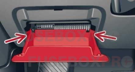
The fuses are located in the driver’s side footwell behind the storage compartment and in the engine compartment.
Cockpit fuse assignment
The fuse number is stamped into the plastic below or above each fuse.
- ► Switch the ignition and all electrical equipment off.
- ► Check the following table to see which fuse belongs to the equipment.
- ► Open the storage compartment.
- ► Press the left and right retainers inward and fold the compartment all the way down
| № | Sunshade on the panorama roof |
| 1 | LED headlight (left) |
| 2 | LED headlight (right) |
| 3 | LED headlight (left) |
| 4 | LED headlight (right) |
| 5 | |
| 6 | |
| 7 | Steering lock |
| 8 | Convenience access |
| 9 | Airbag control module, AIRBAG OFF indicator light |
| 10 | |
| 11 | |
| 12 | Transmission control module |
| 13 | Air quality sensor for climate control system, heated window washer nozzles,  button, reverse light button button, reverse light button , oil level sensor, climate control system, seat occupant detection system, seat heating, buttons in the center console, automatic dimming mirror , oil level sensor, climate control system, seat occupant detection system, seat heating, buttons in the center console, automatic dimming mirror |
| 14 | Engine control module, transmission control module, quattro control module, brake lights, electromechanical steering, Gateway control module, trailer hitch control module, ESC control module, light switch, damping control module |
| 15 | Headlight range control module, instrument illumination, headlights (left, right), diagnostic connector, headlight range control module, crankcase housing heater, air flow sensor, socket relay, DC/DC converter |
| 16 | Parking system |
| 17 | Parking system rearview camera |
| 18 | TV tuner |
| 19 | Engine starter control, DC/DC converter |
| 20 | ESC control module, climate/heating control, special functions interface |
| 21 | Selector mechanism power supply |
| 22 | Interior monitoring |
| 23 |  button, front interior lighting buttons, diagnostic connector, light switch, light/ rain sensor, humidity sensor button, front interior lighting buttons, diagnostic connector, light switch, light/ rain sensor, humidity sensor |
| 24 | |
| 25 | Headlight power supply |
| 26 | Rear window wiper |
| 27 | Starter system |
| 28 | Infotainment |
| 29 | Supply for the parking system rearview camera and TV tuner |
| 30 | Infotainment |
| 31 | Infotainment |
| 32 | Instrument cluster |
| 33 | Automatic dimming rearview mirror |
| 34 | |
| 35 | |
| 36 | Cigarette lighter, cockpit/luggage compartment socket |
| 37 | Cockpit/rear socket |
| 38 | Transmission control module |
| 39 | |
| 40 | Trailer hitch control module |
| 41 | Trailer hitch control module |
| 42 | Trailer hitch control module |
| 43 | |
| 44 | Rear window defogger |
| 45 | Electromechanical parking brake control module |
| 46 | Trailer hitch control module |
| 47 | quattro control module |
| 48 | Automatic luggage compartment lid control module |
| 49 | |
| 50 | Fan |
| 51 | Electromechanical parking brake control module |
| 52 | BCM |
| 53 | Front seat heating |
| 54 | Panorama roof |
| 55 | Sun shade on the panorama roof |
| 56 | Adaptive dampers control module |
Engine compartment fuse assignment
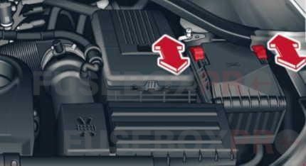
The fuse number is stamped into the plastic below or above each fuse.
- ► Switch the ignition and all electrical equipment off.
- ► Check the following table to see which fuse belongs to the equipment.
- ► To release the fuse panel cover, slide both sliding retainers at the left and right forward.
- ► Remove the fuse panel cover.
| № | Assignment/Designation |
| 1 | Transmission supply |
| 2 | ESC |
| 3 | Horn |
| 4 | DC/DC converter |
| 5 | BCM, battery data module |
| 6 | BCM (right) |
| 7 | Washer fluid pump |
| 8 | BCM (left) |
| 9 | Seat adjustment lumbar support |
| 10 | Heat oxygen sensor |
| 11 | Steering column lever, multifunction steering wheel controls |
| 12 | Cell phone adapter |
| 13 | Engine control module |
| 14 | Engine control module |
| 15 | Gateway |
| 16 | Heated oxygen sensor, fuel pump, engine components |
| 17 | Engine components |
| 18 | Fuel pump control module |
| 19 | Sound amplifier, DC/DC converter |
| 20 | Clutch pedal sensor, brake light sensor |
| 21 | |
| 22 | Windshield wipers |
| 23 | Water circulation pump, auxiliary heater |
| 24 | Ignition coils |
| 25 | Driver’s door control module (central locking, window regulators) |
| 26 | Front passenger’s door control module (central locking, window regulators) |
| 27 | Terminal 15 supply |
| 28 | |
| 29 | Power seat adjustment |
| 30 | ESC |
The Audi Q3 2011-2016 is an exceptional luxury subcompact SUV that offers excellent performance, comfort, and versatility. The car’s advanced features and technological advancements make it stand out from other SUVs in its class. The fuse box and relay system are crucial components of the car’s electrical system, ensuring that all the electrical components are functioning correctly. Proper maintenance of the fuse box and relay system is essential for the optimal performance of the car.

