The Audi A5 is a luxury coupe introduced in 2007 and produced until 2012. It is renowned for its sleek and sporty design, advanced technology, and impressive performance. The A5 comes in both a coupe and convertible body style, and is available with a range of engines including a turbocharged 2.0-liter four-cylinder, a supercharged 3.0-liter V6, and a powerful 4.2-liter V8. The car’s precise handling, strong acceleration, and luxurious interior make it a popular choice among car enthusiasts.
One of the most important components of any vehicle is the electrical system, and the Audi A5 is no exception. The car is equipped with a complex network of electrical components including the fuse box and relays, which are responsible for ensuring that all of the car’s electronic systems function correctly. In this article, we will take a closer look at the fuse box and relay diagrams of the Audi A5, and explore how these important components work to keep the car’s electrical system running smoothly.
Fuse Box and Relay Diagrams of the Audi A5 2007-2012
The Audi A5 is equipped with two fuse boxes located in different areas of the vehicle. The first fuse box is located in the engine compartment on the driver’s side, and is responsible for controlling the car’s main electrical systems. The second fuse box is located in the passenger compartment on the driver’s side, and is responsible for controlling the car’s secondary electrical systems.
Each fuse box contains a diagram that indicates the location of each fuse and relay, and the function of each component. The diagrams are typically printed on the underside of the fuse box covers, making them easy to access and reference when necessary. In addition to the fuse boxes, the Audi A5 is also equipped with a number of relays that help to control various electrical systems including the air conditioning, fuel pump, and horn. These relays are located throughout the vehicle and are also indicated on the fuse box diagrams. Understanding the location and function of these components is essential for maintaining and troubleshooting the electrical system of the Audi A5.
(2007-2012) Audi A5 fuse box and relay with Diagram
WARNING
- Never replace a fuse with one that has a higher amperage rating.
- A fuse with a too-high amperage could damage the electrical part and cause a fire.
- On no account should fuses be repaired (e.g. patched up with tin foil or wire) as this may cause serious damage elsewhere in the electrical circuit or cause a fire.
- If a fuse blows repeatedly, do not keep replacing it. Instead, have the cause for the repeated short circuit or overload tracked and fixed.
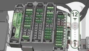
Audi A5 2007-2012 Fuse Location, Instrument Panel left
The fuses are located at the front left and right of the cockpit and behind the trim on the right side of the luggage compartment.
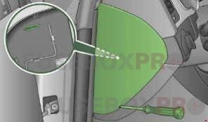
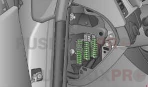
Fuse Location, Instrument Panel left
Some of the equipment items listed are optional or only available on certain model configurations.
Note that the following table is accurate at the time of going to press and is subject to change. In the event of discrepancies, the label on the inside of the cover always takes precedence.
The power seats are protected by circuit breakers, which automatically reset after a few seconds after the overload has been remedied.
| Fuse panel A (black) | ||
| № | Assignment/Designation | Amps |
| 1 | Dynamic steering | 5A |
| 2 | Not used | – |
| 3 | HomeLink | 5A |
| 4 | – | – |
| 5 | Climate control | 5A |
| 6 | Right headlight range adjustment | 5A |
| 7 | Left headlight range adjustment | 5A |
| 8 | Vehicle electrical system control module 1 | 5A |
| 9 | Adaptive cruise control | 5A |
| 10 | Shift gate | 5A |
| 11 | Heater washer fluid nozzles | 5A |
| 12 | Climate control | 5A |
| 13 | Cell phone prep | 5A |
| 14 | Airbag | 5A |
| 15 | Terminal 15 | 25A |
| 16 | Terminal 15 engine | 40A |
| Fuse panel B (brown) | ||
| 1 | Automatic dimming interior rearview mirror | 5A |
| 2 | Clutch sensor | 5A |
| 3 | Gasoline fuel pump | 25A |
| 4 | Auxiliary water pump 3.2L FSI | 5A |
| 5 | Left seat heating with/without seat heating | 15/30A |
| 6 | Electronic Stabilization Control | 10A |
| 7 | Horn | 25A |
| 8 | Left door window regulator motor | 30A |
| 9 | Wiper motor | 30A |
| 10 | Electronic Stabilization Control | 25A |
| 11 | Left doors | 15A |
| 12 | Rain and light sensor | 5A |
| Fuse panel C (red) | ||
| 1 | – | – |
| 2 | – | – |
| 3 | Lumbar support | 10A |
| 4 | Dynamic steering | 35A |
| 5 | Climatized cupholder | 10A |
| 6 | Vehicle electrical system control module 1 | 35A |
| 7 | Vehicle electrical system control module 1 | 20A |
| 8 | Vehicle electrical system control module 1 | 30A |
| 9 | Panorama sunroof | 20A |
| 10 | Vehicle electrical system control module 1 | 30A |
| 11 | Panorama sunroof shade | 20A |
| 12 | Convenience electronics | 5A |
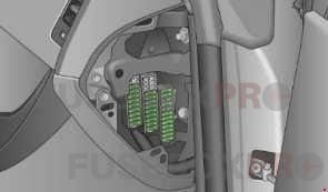
Fuse Location, Instrument Panel right
Some of the equipment items listed are optional or only available on certain model configurations.
Note that the following table is accurate at the time of going to press and is subject to change. In the event of discrepancies, the label on the inside of the cover always takes precedence.
The power seats are protected by circuit breakers, which automatically reset after a few seconds after the overload has been remedied.
| Fuse panel A (black) | ||
| № | Assignment/Designation | Amps |
| 1 | – | – |
| 2 | – | – |
| 3 | – | – |
| 4 | – | – |
| 5 | Steering column switch module | 5A |
| 6 | Electronic Stabilization Program | 5A |
| 7 | Terminal 15 diagnostic connector | 5A |
| 8 | Gateway | 5A |
| 9 | – | – |
| 10 | – | – |
| 11 | – | – |
| 12 | – | – |
| Fuse panel B (brown) | ||
| 1 | CD/DVD player | 5A |
| 2 | Audi drive select switch module | 5A |
| 3 | MMI/Radio | 5/20A |
| 4 | Instrument cluster | 5A |
| 5 | Gateway | 5A |
| 6 | Ignition lock | 5A |
| 7 | Rotary light switch | 5A |
| 8 | Climate control system blower | 40A |
| 9 | Steering column lock | 5A |
| 10 | Climate control system | 10A |
| 11 | Terminal 30 diagnostic connector | 10A |
| 12 | Steering column switch module | 5A |
Fuse Location, Luggage Compartment right
Read the numbers of the fuses in the luggage compartment starting from inside.
| Fuse panel A (black) | ||
| № | Assignment/Designation | Amps |
| 1 | – | |
| 2 | Rear window heater (Cabriolet) | |
| 3 | Power top latch (Cabriolet) | |
| 4 | Power top hydraulics (Cabriolet) | |
| Fuse panel B (black) | ||
| 1 | Luggage compartment lid control module (Avant) | 30 |
| 2 | Trailer control module | 15A |
| 3 | Trailer control module | 20A |
| 4 | Trailer control module | 20A |
| 5 | Electromechanical parking brake | 5A |
| 6 | Electronic damping control | 15A |
| 7 | Electromechanical parking brake | 30A |
| 8 | Vehicle electrical system control module 2 | 30A |
| 9 | Quattro sport | 35A |
| 10 | Vehicle electrical system control module 2 | 30A |
| 11 | Vehicle electrical system control module | 20A |
| 12 | Terminal 30 | 5A |
| Fuse panel C (brown) | ||
| 1 | Luggage compartment lid control module | 30A |
| 2 | Right front seat heating | 15A |
| 3 | DCDC converter path 1 | 40A |
| 4 | DCDC converter path 2 | 40A |
| 5 | Socket | 30A |
| 6 | – | – |
| 7 | Electromechanical parking brake | 30A |
| 8 | Rear seat heating | 30A |
| 9 | Passenger side door control module | 30A |
| 10 | – | – |
| 11 | Passenger side door control module | 15A |
| 12 | Cell phone prep | – |
| Fuse panel D (red) | ||
| 1 | Rear center console outlet | 15A |
| 2 | Front center console outlet | 15A |
| 3 | Luggage compartment outlet | 15A |
| 4 | Cigarette lighter | 15A |
| 5 | V6 FSI | 5A |
| 6 | Rear Seat Entertainment supply | 5A |
| 7 | Parking system | 7.5A |
| 8 | Rear wiper (Avant) | 15A |
| 9 | Electromechanical parking brake switch | 5A |
| 10 | Audi side assist | 5A |
| 11 | Rear seat heating | 5A |
| 12 | Terminal 15 control modules | 5A |
| Fuse panel E (black) | ||
| 1 | Not used | – |
| 2 | Not used | – |
| 3 | DSP amplifier, radio | 30/20A |
| 4 | MMI | 7.5A |
| 5 | Radio/Navigation/cell phone prep | 7.5A |
| 6 | Rearview camera | 5A |
| 7 | Not used | – |
| 8 | Not used | – |
| 9 | Not used | – |
| 10 | Not used | – |
| 11 | Not used | – |
| 12 | Not used | – |
In conclusion, the Audi A5 2007-2012 is a sleek and powerful luxury coupe that offers impressive performance and advanced technology. The car’s electrical system is a complex network of components that are responsible for ensuring that all of the car’s electronic systems function correctly. The fuse box and relay diagrams are an important part of this system, as they help to identify the location and function of each component. By understanding the location and function of these components, Audi A5 owners can ensure that their car’s electrical system is running smoothly, and quickly troubleshoot any problems that may arise.