The Audi A3 is a compact luxury car produced by the German automaker Audi since 1996. The third-generation A3 is introduced in 2012 and continued production until 2016. The A3 is offered as a three-door hatchback or a five-door Sportback, and is available with a variety of gasoline and diesel engines. The car has a sleek and sporty design, advanced technology features, and excellent handling capabilities.
In this article, we will focus on the electrical components of the Audi A3 2012-2016, specifically the fuse box and relay diagrams with locations. These components play an important role in the proper functioning of the car’s electrical system, including the headlights, air conditioning, power windows, and more. By understanding these components and their locations, Audi A3 owners can troubleshoot and fix electrical problems more easily.
Fuse Box Diagram and Location
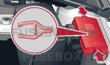
The Audi A3 2012-2016 has two fuse boxes – one in the engine compartment and one in the cabin. The engine compartment fuse box is located on the driver’s side, near the battery. The cabin fuse box is located on the left side of the dashboard, behind a cover.
The fuse box contains fuses that protect various electrical components from damage due to electrical surges or short circuits. Each fuse is labeled with its amperage rating and the electrical component it protects. For example, the 15A fuse in position 5 of the engine compartment fuse box protects the windshield washer pump, while the 30A fuse in position 10 of the cabin fuse box protects the power windows.
Relay Diagram and Location
Relays are another important electrical component of the Audi A3 2012-2016. Relays are switches that are activated by an electrical signal and control the flow of electricity to various components in the car. The A3 has several relays located throughout the car, including in the engine compartment and under the dashboard.
The relay diagram is usually located on the inside of the cover of the fuse box. The diagram shows the location of each relay and its function. For example, the relay in position 3 of the engine compartment relay box controls the cooling fan, while the relay in position 12 of the cabin relay box controls the power windows.
By referring to the fuse box and relay diagrams with locations, Audi A3 owners can identify and troubleshoot electrical problems more easily. Whether it’s a blown fuse or a faulty relay, understanding these components is essential to maintaining the proper functioning of the car’s electrical system.
(2012-2016) Audi A3 fuse box and relay with Diagram
WARNING
- Never replace a fuse with one that has a higher amperage rating.
- A fuse with a too-high amperage could damage the electrical part and cause a fire.
- On no account should fuses be repaired (e.g. patched up with tin foil or wire) as this may cause serious damage elsewhere in the electrical circuit or cause a fire.
- If a fuse blows repeatedly, do not keep replacing it. Instead, have the cause for the repeated short circuit or overload tracked and fixed.
Audi A3 2012-2016 Cockpit fuse assignment
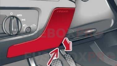
The fuses are located under the steering wheel behind a cover and in the left side of the engine compartment.
Fuses in the interior
The fuses are behind the cover in the steering column area.
Some of the equipment listed in the following tables applies only to certain model versions or certain optional equipment.
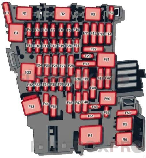
| № | Assignment/Designation |
| 1 | Engine components |
| 2 | Seat adjustment |
| 3 | Hydraulic pump cover (Cabriolet) |
| 4 | MMI control panel, MMI components |
| 5 | Gateway |
| 6 | Selector lever (automatic transmission) |
| 7 | Climate/heating control, auxiliary heating, rear window defogger relay |
| 8 | Diagnosis, electromechanical parking brake switch, light switch, rain and light sensor, interior lighting communication box (Plug-in hybrid drive*) anti-theft alarm system |
| 9 | Steering column switch module |
| 10 | Display |
| 11 | Reversible driver’s side safety belt tensioners |
| 12 | MMI area |
| 13 | Adaptive dampers control module/service plug (Plug-in hybrid drive*) |
| 14 | Climate control system blower |
| 15 | Electronic steering column lock |
| 16 | MMI area |
| 17 | Instrument cluster |
| 18 | Rearview camera |
| 19 | Convince key system control module, tank system |
| 20 | Tank system |
| 21 | – |
| 22 | – |
| 23 | Exterior lighting, heated washer fluid nozzles |
| 24 | Panorama sunroof/power top control module, power top latch (Cabriolet) |
| 25 | Door/driver’s side doors (for example power windows) |
| 26 | Seat heating |
| 27 | Sound-amplifier |
| 28 | Power top control module, electronics (Cabriolet) |
| 29 | Interior lights |
| 30 | – |
| 31 | Exterior lighting |
| 32 | Driver assistance systems |
| 33 | Airbag |
| 34 | Button illumination, coils for upper cabin heating relay (Cabriolet) and socket relay, interior sound, reversing light switch, temperature sensor |
| 35 | Function lighting, diagnosis, headlight range control system, air quality sensor, automatic dimming rearview mirror |
| 36 | Right cornering light / right LED-headlight |
| 37 | Left cornering light / left LED-headlight |
| 38 | High-voltage battery (Plug-in hybrid drive*) |
| 39 | Door/front passenger’s side doors (for example, power windows) |
| 40 | Sockets |
| 41 | Reversible front passenger’s side safety belt tensioners |
| 42 | Central locking components, windshield washer system |
| 43 | Fleadlights, lighting |
| 44 | All wheel drive |
| 45 | – |
| 46 | – |
| 47 | Rear window wiper |
| 48 | Outer noise amplifier (Plug-in hybrid drive*) |
| 49 | Starter, clutch sensor, headlight relay coil, high-voltage battery (Plug-in hybrid drive*) |
| 50 | – |
| 51 | – |
| 52 | – |
| 53 | Rear window defogger |
The power seats* are protected via circuit breakers that automatically switch on after a few seconds after the overload has been reduced.
Fuses in the engine compartment
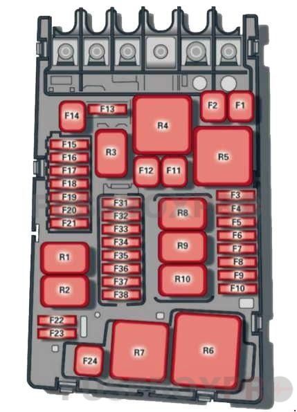
| № | Assignment/Designation |
| 1 | ESC control module |
| 2 | ESC control module |
| 3 | Engine control module (gasoline/diesel) |
| 4 | Engine cooling, engine components, auxiliary heater coil relay (1+2), secondary air injection pump relay |
| 5 | Engine components, tank system |
| 6 | Brake light sensor |
| 7 | Engine components, water pumps |
| 8 | Oxygen sensor |
| 9 | Engine components, exhaust door, glow time control module, SULEV valve |
| 10 | Fuel injectors, fuel control module |
| 11 | Auxiliary heater heating element 2 |
| 12 | Auxiliary heater heating element 3 |
| 13 | Automatic transmission control module |
| 14 | – |
| 15 | Horn |
| 16 | Ignition coil/power electronics (Plug-in hybrid drive*) |
| 17 | ESC control module, engine control module |
| 18 | Terminal 30 (reference voltage) |
| 19 | Windshield wipers |
| 20 | Horn |
| 21 | – |
| 22 | Terminal 50 diagnosis |
| 23 | Starter |
| 24 | Auxiliary heater heating element 1, brake booster (Plug-in hybrid drive*) |
| 25 | – |
| 26 | – |
| 27 | – |
| 28 | – |
| 29 | – |
| 30 | – |
| 31 | Vacuum pump/water pump (Plug-in hybrid drive*) |
| 32 | LED headlights |
| 33 | Brake booster memory (Plug-in hybrid drive*) |
| 34 | Brake booster control (Plug-in hybrid drive*) |
| 35 | Relay (Plug-in hybrid drive*) |
The power seats* are protected via circuit breakers that automatically switch on after a few seconds after the overload has been reduced.