
The BMW X5 (F15) is a luxury mid-size SUV that is produced by the German automaker BMW from 2010 to 2015. It is renowned for its powerful performance, luxurious features, and advanced technology. As with any modern vehicle, the BMW X5 (F15) incorporates various electrical components that play a crucial role in its functionality and performance. In this article, we will explore the electrical system of the BMW X5 (F15) with a specific focus on the fuse box and relay diagrams, highlighting their locations and functions within the vehicle.
Fuse Box and Relay Overview
The fuse box and relay system of the BMW X5 (F15) is an integral part of the vehicle’s electrical infrastructure. Located in the engine compartment, the fuse box houses a series of fuses and relays that protect and control different electrical circuits in the vehicle. The fuses act as safety devices, preventing electrical overload and potential damage to various components. The relays, on the other hand, serve as switches, enabling the flow of electricity to different systems and components when required.
The fuse box and relay system of the BMW X5 (F15) is designed with efficiency and organization in mind. Each fuse and relay is labeled according to its corresponding circuit, making it easier for technicians and owners to identify and replace them if necessary. The fuse box and relay diagrams provide a visual representation of the fuse locations and relay assignments, assisting in diagnosing and troubleshooting electrical issues within the vehicle.
Functions and Common Issues
The fuse box and relay system of the BMW X5 (F15) control various electrical components and systems, ensuring their proper functioning. Some of the primary functions include managing the vehicle’s lighting system, powering the audio and entertainment system, regulating the air conditioning and heating system, and controlling engine-related components.
While the fuse box and relay system of the BMW X5 (F15) are designed to be reliable, occasional issues may arise. Common problems include blown fuses due to electrical surges or component failures, malfunctioning relays causing system failures, or loose connections leading to intermittent electrical issues. It is crucial to have a thorough understanding of the fuse box and relay diagrams to locate and address these issues effectively. Regular inspection, maintenance, and timely replacement of faulty fuses and relays can help maintain the electrical integrity of the BMW X5 (F15) and ensure its optimal performance.
(2013-2018) BMW X5 (F15) fuse box and relay with Diagram
WARNING
- Never replace a fuse with one that has a higher amperage rating.
- A fuse with a too-high amperage could damage the electrical part and cause a fire.
- On no account should fuses be repaired (e.g. patched up with tin foil or wire) as this may cause serious damage elsewhere in the electrical circuit or cause a fire.
- If a fuse blows repeatedly, do not keep replacing it. Instead, have the cause for the repeated short circuit or overload tracked and fixed.
BMW X5 (F15) 2010-2015 fuse assignment
Luggage Compartment Fuse Box
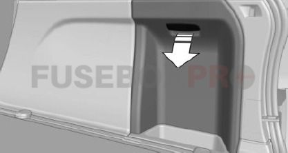
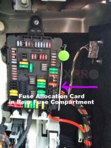
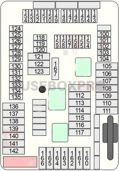
| No. | Amps | Assignment/Designation |
| 100 | 5A | Parking Brake Button |
| 101 | 15A | Right Headlight |
| 102 | 5A | High-Voltage Battery Unit |
| 103 | 5A | Siren with Tilt Alarm Sensor |
| 104 | 5A | Parking Brake Control Unit, Natural Vacuum Leak Detection (NVLD) |
| 105 | 30A | Reversible Electromotive Automatic Reel (Right) |
| 106 | 30A | Rear Axle Lateral Torque Distribution |
| 107 | 40A | Automatic Luggage Compartment Lid Actuation (>07.2016), Tailgate Function Module (08.2016>) |
| 108 | – | – |
| 109 | – | – |
| 110 | 40A | Air Suspension Compressor Relay |
| 111 | – | – |
| 112 | 20A | Pressurised Fuel Tank Control Module |
| 113 | 30A | Trailer Module |
| 114 | 30A | Trailer Module |
| 115 | 20A | Right Headlight |
| 116 | 30A | Parking Brake Control Unit |
| 117 | 30A | Reversible Electromotive Automatic Reel (Left) |
| 118 | 5A | Video Switch (VSW) |
| 119 | – | – |
| 120 | 5A | Power Control Unit |
| 5A | N20: Charging Controller for Auxiliary Battery | |
| 121 | 20A | Headunit |
| 122 | 30A | Audio Amplifier |
| 123 | – | – |
| 124 | 5A | Video Module |
| 125 | – | – |
| 126 | 10A | Rear Passenger’s Door Automatic Soft-Close Drive |
| 127 | 5A | DVD-Changer |
| 128 | 5A | Wireless Charging Oddments Tray, Antenna Amplifier, Base Plate |
| 129 | 15A | Active Sound Design (ASD) |
| 130 | 5A | Automatic Luggage Compartment Lid Actuation |
| 131 | 5A | Luggage Compartment Light, Rear Lid Button on Inside of Rear Lid, Noise Suppressor Filter |
| 132 | 5A | Rear Axle Lateral Torque Distribution, Electronic Ride Height Control |
| 133 | 5A | Rear Compartment Automatic Climate Control |
| 134 | 5A | Rear Driver’s Door Automatic Soft-Close Drive |
| 135 | 5A | Safety Battery Terminal Gas Generator |
| 136 | – | – |
| 137 | – | – |
| 138 | – | – |
| 139 | 20A | Trailer Socket |
| 140 | 20A | Boot Lid/Tailgate Lock |
| 141 | – | – |
| 142 | – | – |
| 143 | 10A | Cool Box Relay |
| 144 | 15A | Selective Catalytic Reduction (SCR) Control Unit |
| 145 | 5A | Parking Assistant, Infotainment Fan No.2 |
| 146 | 15A | Electrical Exhaust Flap (No.1, No.2) |
| 147 | 15A | Selective Catalytic Reduction (SCR) Control Unit |
| 148 | 5A | Lane Change Warning (SWW) |
| 149 | 7.5A | Right Headlight |
| 150 | 5A | →06.2016: Contact-Free Tailgate Opening Evaluation Electronics, Convenience Charging Electronics |
| 7.5A | 07.2016→: Contact-Free Tailgate Opening Evaluation Electronics, Convenience Charging Electronics, Tailgate Function Module | |
| 151 | 5A | USB-HUB (USB Connection No.1/No.2, AUX-In Connection) |
| 152 | 5A | Reversible Electromotive Automatic Reel (Left/Right) |
| 153 | 15A | Selective Catalytic Reduction (SCR) Control Unit |
| 154 | 5A | All-Round Vision Camera (TRSVC), Reversing Camera |
| 155 | 10A | Passenger’s Door Automatic Soft-Close Drive |
| 156 | 10A | Driver’s Door Automatic Soft-Close Drive |
| 157 | – | – |
| 158 | 10A | Rear Seat Entertainment |
| 159 | 5A | Audio Amplifier, Infotainment Fan No.2 |
| 160 | 20A | Rear Compartment Blower Motor |
| 161 | – | – |
| 162 | 20A | Rear Cigarette Lighter (12V Connection No.1 & No.2), Luggage Cigarette Lighter (12V Connection) |
| 163 | 30A | Trailer Module |
| 164 | 30A | Right Rear Seat Heating Module |
| 165 | 20A | Fuel Pump Control (EKPS) |
| 166 | 30A | Left Rear Seat Heating Module |
| 167 | 30A | Driver’s Door Automatic Soft-Close Drive, Passenger’s Door Automatic Soft-Close Drive |
Passenger Compartment Fuse Box
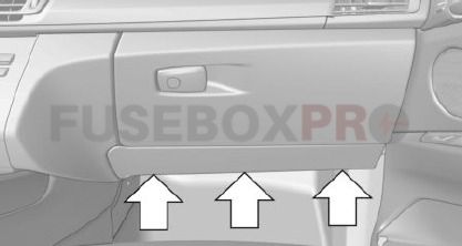
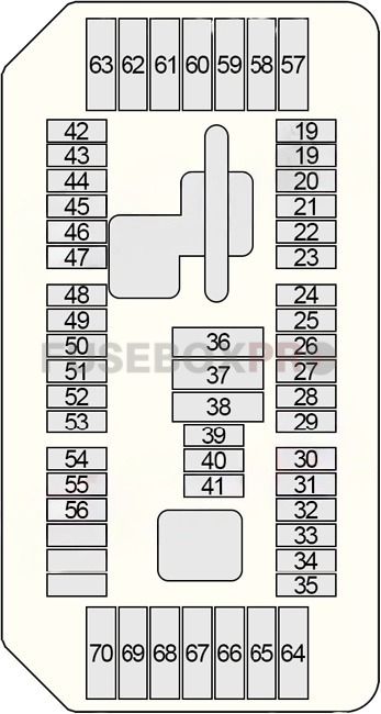
| No. | Amps | Assignment/Designation |
| 19 | 5A | Remote Control Receiver |
| 20 | 5A | Roof Function Control Centre |
| 21 | 5A | Preheating Control Unit |
| 22 | 7.5A | Driver’s Door Switch Block, Passenger Exterior Mirror |
| 23 | 10A | Digital Motor Electronics (DME) |
| 24 | 10A | Electronic Transmission Control |
| 25 | 5A | Touchbox, iDrive Controller |
| 26 | 5A | Extendible Dashboard Speaker, Rear Left/Right Seat Heating Switch |
| 27 | 10A | Driver/Passenger Lumbar Support Valve Block, Driver’s/Passenger’s Side Seat Adjustment Switch |
| 28 | 5A | Rain/Light/Solar/Condensation Sensor, Roof Function Control Centre, Vanity Mirror Lights |
| 29 | 15A | Auxiliary Water Pump |
| 30 | 10A | Coolant Pump for Charge Air Cooler |
| 31 | 5A | Electric Fan Cut-Out Relay |
| 32 | 5A | Transfer Box |
| 33 | 5A | N63, S63: Turbocharger Coolant Pump |
| 5A | N20: A/C Compressor (Electrical), Electric Auxiliary Heater | |
| 34 | 5A | Integrated Chassis Management (ICM) |
| 35 | 5A | Electrochromic Interior Rear View Mirror |
| 36 | 20A | Centre Power Socket (12V Connection) |
| 37 | 20A | Front Cigarette Lighter (12V Connection) |
| 38 | 20A | Roof Function Control Centre |
| 39 | 15A | Left Headlight |
| 40 | – | – |
| 41 | 10A | S63: Coolant Pump for Charge Air Cooler |
| 10A | N20: Passenger Compartment Refrigerant Shutoff Valve, Electric-Machine Electronics (EME) | |
| 42 | 5A | Electronic Damper Control, Electrochromic Interior Rear View Mirror |
| 43 | 5A | Left/Right Targeted Illumination |
| 44 | 7.5A | Camera-Based Driver Assistance Systems (KAFAS), Active Steering |
| 45 | 5A | Active Cruise Control (ACC), Automatic Air Recirculation Control Sensor (AUC) |
| 46 | 5A | Radiator Shutter Drive Unit |
| 5A | B47, N47, N57: Engine Breather Heater, Radiator Shutter Drive Unit | |
| 47 | 5A | Electronic Night Vision Module (NVE), Vehicle Sound Generator (VSG) |
| 48 | 10A | Steering Column Switch Center |
| 49 | 5A | Steering Angle Sensor |
| 5A | N57D30T1: Shutoff Valve for Coolant Expansion Tank, Steering Angle Sensor | |
| 50 | 5A | Instrument Cluster |
| 51 | – | – |
| 52 | 7.5A | Instrument Cluster |
| 53 | 5A | Glove Compartment Light, Decor Strip Lighting, Door Pocket Lighting, Door Panel Lighting, Front Left/Right Footwell Light |
| 54 | 10A | Gear Selector Switch (GWS) |
| 55 | 5A | Servotronic (SVT), Electromechanical Power Steering (EPS) |
| 56 | 5A | Vertical Dynamics Management (VDM) |
| 57 | 20A | Left Headlight |
| 58 | 30A | Dynamic Stability Control (DSC) |
| 59 | 40A | Active Steering |
| 60 | 40A | Blower Output Stage |
| 61 | 20A | Electronic Damper Control |
| 62 | 30A | →06.2016: Vertical Dynamics Management (VDM) |
| 20A | 07.2016→: Vertical Dynamics Management (VDM) | |
| 63 | 30A | Transfer Box (VTG) |
| 64 | 30A | Passenger’s Seat Heating Module |
| 65 | 30A | Driver’s Seat Heating Module |
| 66 | 20A | Independent Auxiliary Heater |
| 67 | 30A | Driver’s Side Seat Adjustment Switch Block (without Seat Module (SMFA)), Driver Seat Module (SMFA) |
| 68 | 30A | Passenger’s Side Seat Adjustment Switch Block (without Seat Module (SMBF)), Passenger’s Seat Module (SMBF) |
| 69 | 20A | Electronic Transmission Control (EGS) |
| 70 | 20A | Electric Steering Column Adjustment |
Passenger Compartment Fuse Box No.2 (BDC – Body Domain Controller)
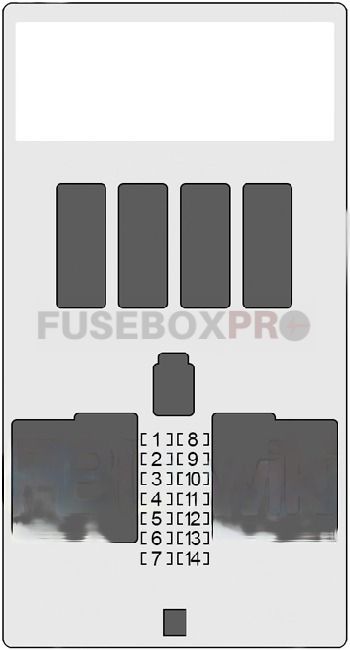
| No. | Amps | Assignment/Designation |
| 1 | 30A | Passenger Power Window Drive |
| 2 | 30A | Driver’s Side Rear Power Window Drive |
| 3 | 20A | Front Passenger Door Lock |
| 4 | 30A | Driver Power Window Drive |
| 5 | 30A | Rear Window Defogger |
| 6 | 30A | Passenger’s Side Rear Power Window Drive |
| 7 | 20A | Driver’s Door Lock |
| 8 | – | – |
| 9 | 5A | Steering Column Switch Center, Light Switch Unit, Driver Assistance System Operating Facility with Hazard Warning Switch |
| 10 | 7.5A | Left Headlight |
| 11 | 7.5A | Diagnostic Connector, Heating/Air Conditioning System, Dynamic Stability Control (DSC) |
| 12 | 5A | Telematic Communication Box, Electronic Outer Doors Handles Module |
| 13 | 15A | Horn (Low/High Range) |
| 14 | – | – |
Engine Compartment Fuse Box
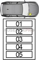
| No. | Amps | Assignment/Designation |
| 01 | 20A | Camshaft Sensor, Fuel Quantity Control Valve, Rail Pressure Regulating Valve, Turbine Control Flap Pressure Converter, Low Pressure Compressor Bypass Flap Changeover Valve (except USA), Auxiliary EGR Cooler Bypass Flap Changeover Valve (USA), Charging Pressure Actuator (Performance Class “T”), High-Pressure Stage Charging Pressure Actuator (VNT – Performance Class “S”), High-Pressure Stage Charging Pressure Actuator No.2 (VNT (N57D30S1)) |
| 02 | 20A | Oxygen Sensor before Catalytic Converter, Hot-Film Air Mass Meter, Engine Mount Changeover Valve, Oxygen Sensor after Catalytic Converter, Oil Condition Sensor, EGR Cooler Bypass Flap Changeover Valve, High Pressure Compressor Actuating Flap Changeover Valve No.2, Pressure Converter for Wastegate Valve |
| 03 | 30A | Digital Diesel Electronics (DDE) |
| 04 | 10A | Nitrogen Oxide Sensor before SCR Catalytic Converter, Coolant Pump EGR Cooling (→04.2014), Changeover Valve for Low-Temperature EGR Cooling, Diesel Particulate Sensor |
| 05 | 10A | Pressure Converter for Wastegate Valve, Changeover Valve of Turbine Control Flap, Coolant Pump Relay |
Fuse Box (Non-Replaceable)
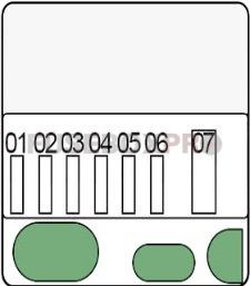
| No. | Amps | Assignment/Designation |
| 01 | 25A | Digital Motor Electronics (DME) – Ignition |
| 02 | 25A | Digital Motor Electronics (DME) – Injector |
| 03 | 15A | Digital Motor Electronics (DME) – Injector |
| 04 | 20A | Digital Motor Electronics (DME) – Injector |
| 05 | 40A | Digital Motor Electronics (DME) – Valvetronic |
| 06 | 40A | Digital Motor Electronics (DME) – Valvetronic |
| 07 | – | – |
| Relay | ||
| R1 | Ignition & Injectors | |
| R2 | Valvetronic | |
| R3 | Digital Motor Electronics (DME) | |
Engine Compartment Fuse Box (Non-Replaceable)
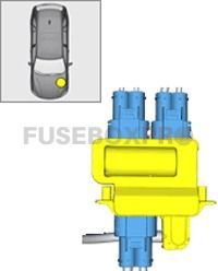
| No. | Amps | Assignment/Designation |
| 400 | 125A | Electric Fan Cut-Out Relay |
| 401 | 125A | Electromechanical Power Steering (EPS) |
| 402 | 100A | Electric Auxiliary Heater |
| 403 | 50A | Fuel Filter Heating |
Fusible Link Block (Non-Replaceable)
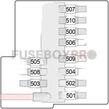
| No. | Amps | Assignment/Designation |
| 500 | 50A | Body Domain Controller (BDC) |
| 501 | 125A | Rear Power Distribution Box |
| 502 | 150A | Dynamic Stability Control (DSC) |
| 503 | 125A | N63, S63, N20: Integrated Supply Module |
| 125A | D47, N47, N57: Digital Diesel Electronics (DDE) Main Relay | |
| 504 | 125A | Body Domain Controller (BDC) |
| 505 | 50A | Audio Amplifier |
| 506 | 60A | N55, N63, S53, B47, N47, N57: Power Control Unit (PCU) |
| 60A | N20: Charging Controller for Auxiliary Battery | |
| 507 | 40A | Rear Right Electric Auxiliary Heater |
| 508 | 40A | 3rd Seat Row Auxiliary Heating Control |
| 509 | 40A | Body Domain Controller (BDC) |
| 510 | 40A | Rear Left Electric Auxiliary Heater |
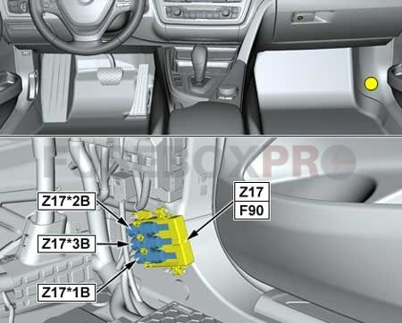
| No. | Amps | Assignment/Designation |
| 90 | 50A | Dynamic Stability Control (DSC) |
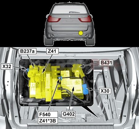
| No. | Amps | Assignment/Designation |
| 540 | 5A | Auxiliary Battery Intelligent Battery Sensor |
Rear Power Distribution Box No.2 (Options)

| No. | Amps | Assignment/Designation |
| 201 | 10A | Auxiliary Control Unit (SEC) |
| 202 | 7.5A | Auxiliary Control Unit (SEC) |
| 203 | 5A | Auxiliary Control Unit (SEC) |
| 204 | 5A | Auxiliary Control Unit (SEC) |
| 205 | 5A | Switch Cluster Auxiliary Module |
| 206 | 5A | Audio Auxiliary Module |
| 207 | 20A | Audio Auxiliary Module |
| 208 | 5A | Audio Auxiliary Module |
| 209 | 5A | Audio Auxiliary Module |
| 210 | 5A | Auxiliary Control Unit (SEC) |
| 211 | 20A | Windscreen Defogger |
| 212 | 20A | Windscreen Defogger |
| 213 | 15A | Heated Side Window (Front Left/Right) |
| 214 | 5A | Auxiliary Control Unit |
| 215 | 5A | Auxiliary Control Unit |
| 216 | 5A | Auxiliary Control Unit |
| 217 | 5A | Audio Auxiliary Module |
| 218 | 5A | Auxiliary Control Unit |
| 219 | 5A | Audio Auxiliary Module |
| 220 | 5A | Auxiliary Control Unit |
Luggage Compartment Fuse Holders

| No. | Amps | Assignment/Designation |
| 301 | 10A | Auxiliary Control Unit |
| 302 | 5A | Switch Cluster Auxiliary Module |
| 303 | 5A | Audio Auxiliary Module |
| 304 | 5A | Auxiliary Control Unit (SEC) |
| 311 | 30A | Power Window |
| 312 | 30A | Power Window |
| 313 | 30A | Power Window |
| 314 | 30A | Power Window |
| 615 | 5A | Electric-Machine Electronics (EME) |
| 612 |
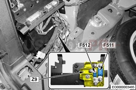
| No. | Amps | Assignment/Designation |
| 511 | 100A | Fuse (without Auxiliary Battery): 301, 302, 303, 304, 311, 312, 313, 314 |
| 100A | Fuse (with Auxiliary Battery): 201, 202, 203, 204, 205, 206, 207, 208, 209, 210, 211, 212, 213, 214, 215, 216, 217, 218 | |
| 512 | 100A | Fuse (without Auxiliary Battery): 301, 302, 303, 304, 311, 312, 313, 314 |
| 100A | Fuse (with Auxiliary Battery): 201, 202, 203, 204, 205, 206, 207, 208, 209, 210, 211, 212, 213, 214, 215, 216, 217, 218 |
The electrical system of the BMW X5 (F15) is a complex and critical aspect of the vehicle, and the fuse box and relay system play a vital role in its operation. Understanding the locations and functions of the fuse box and relays, as depicted in the diagrams, can help owners and technicians diagnose and resolve electrical issues efficiently. Regular inspection, proper maintenance, and prompt replacement of faulty fuses and relays are essential to keep the BMW X5 (F15) running smoothly and enjoying its luxurious features and advanced technology for years to come.
Leave a Reply