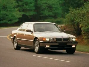
The BMW 7-Series E38 is a full-size luxury car that is produced by BMW from 1994 to 2001. This car is a significant upgrade from the previous BMW E32 model and is designed to provide drivers with a more comfortable and luxurious experience. The E38 is equipped with advanced technology and various electrical components that were responsible for its high performance and comfortable ride. In this article, we will explore the various electrical components of the BMW 7-Series E38, including the fuse box and relay diagrams with locations.
The Fuse Box
The fuse box is an essential component of any car as it helps to protect the electrical system from damage caused by electrical overloads or short circuits. In the BMW 7-Series E38, the fuse box is located in the engine compartment, on the right-hand side. The fuse box contains various fuses that are responsible for protecting different electrical systems of the car, such as the air conditioning system, audio system, and lighting system.
It is essential to ensure that the correct type of fuse is used for each electrical component to prevent any electrical damage to the car. If a fuse blows out, it can be easily replaced by locating the appropriate fuse on the diagram provided on the fuse box cover. The diagram shows the location and function of each fuse, making it easy to identify the correct fuse for replacement.
The Relay
The relay is another important electrical component of the BMW 7-Series E38. The relay is responsible for controlling the electrical flow to various systems of the car, such as the engine, air conditioning, and lighting systems. The relay is located in the engine compartment, on the left-hand side, and can be easily identified by its black color and shape.
If a relay fails, it can result in the malfunctioning of the associated electrical system. To prevent this from happening, it is essential to regularly check and replace any faulty relays. The relay diagram is located on the fuse box cover and shows the location and function of each relay. This makes it easy to identify the correct relay for replacement.
(1994-2001) BMW 7-Series (E38) fuse box and relay with Diagram
WARNING
- Never replace a fuse with one that has a higher amperage rating.
- A fuse with a too-high amperage could damage the electrical part and cause a fire.
- On no account should fuses be repaired (e.g. patched up with tin foil or wire) as this may cause serious damage elsewhere in the electrical circuit or cause a fire.
- If a fuse blows repeatedly, do not keep replacing it. Instead, have the cause for the repeated short circuit or overload tracked and fixed.
BMW 7-Series (E38) 1994-2001 fuse assignment
Engine Compartment Fuse Box (only LHD)
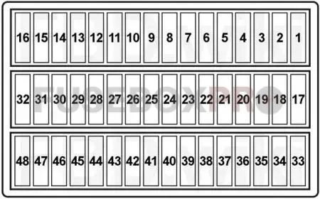
| No. | Amps | Assignment/Designation |
| 1 | – | – |
| 2 | – | – |
| 3 | 30A | Wiper Relay |
| 4 | 30A | Headlight Washer Module |
| 5 | 15A | Horn Relay |
| 6 | 20A | General Module |
| 7 | 7.5A | Water Valves, Auxiliary Water Pump, Independent Heating Receiver, Radio Clock Receiver, Front Shutoff Valve (750iXL) |
| 8 | 30A | Passenger’s Door Module |
| 9 | 20A | Auxiliary Fan Stage 1 Relay |
| 10 | 5A | Visual Entry Aid Relay |
| 25A | 1994→?: ABS/ASC Control Unit | |
| 11 | 15A | Heating and A/C Control Module |
| 30A | 1994→01.1995 (without Memory): Front Passenger’s Seat Adjustment Switch, Passenger’s Back-Rest Adjustment Switch, Switch for Passenger’s Seat Thigh Support, Passenger’s Seat Lumbar Support Switch | |
| 30A | 1994→01.1995 (with Memory): Front Passenger’s Active Seat Control Unit, Passenger’s Seat Movement Motor, Passenger’s Seat Height Adjustment Motor, Passenger’s Seat Cushion Tilt Motor, Passenger’s Backrest Recliner Motor, Passenger’s Seat Memory Control Unit, Passenger’s Back-Rest Actuator Motor, Passenger’s Headrest Motor | |
| 12 | 15A | 01.1995-09.1995: Steering Column Adjustment Control Unit |
| 13 | 20A | 1994→01.1995: Steering Column Adjustment Control Unit |
| 14 | 10A | 1994→01.1995: Rear Headrest Control Unit |
| 5A | Left B-Pillar Light, Right B-Pillar Light, B-Pillar Lights Relay | |
| 15 | 30A | Steering Column Inclination Motor, Steering Column Adjustment Motor, Driver’s Seat Movement Motor, Driver’s Seat Height Adjustment Motor, Driver’s Seat Cushion Tilt Motor, Driver’s Backrest Recliner Motor, Driver’s Headrest Motor, Seat/Steering Column Memory (SM/LSM) Control Unit, Driver’s Thigh Support Motor, Driver’s Back-Rest Actuator Motor, Driver’s Seat Lumbar Support Switch, Driver’s Active Seat Control Unit |
| 16 | 10A | 1994→01.1995: Sunshade Control Unit, Sunshade Switch |
| 30A | 01.1995→ (without Memory):Front Passenger’s Seat Adjustment Switch, Passenger’s Back-Rest Adjustment Switch, Switch for Passenger’s Seat Thigh Support, Passenger’s Seat Lumbar Support Switch | |
| 30A | 01.1995→ (with Memory): Front Passenger’s Active Seat Control Unit, Passenger’s Seat Movement Motor, Passenger’s Seat Height Adjustment Motor, Passenger’s Seat Cushion Tilt Motor, Passenger’s Backrest Recliner Motor, Passenger’s Seat Memory Control Unit, Passenger’s Back-Rest Actuator Motor, Passenger’s Headrest Motor | |
| 17 | 10A | Fuel Pump Relay No.1, Switching Centre, ABS/ASC Control Unit, Steering Angle Sensor, Active Cruise Control (ACC) Control Unit, Charcoal Filter Valve, Fuel Changeover Circuit, Leakage Diagnosis Pump, Secondary Air Pump Relay, Control Unit for Electrically Heated Catalytic Converter |
| 10A | M51, M52, M60: ASC/DSC System Switch, Starter Relay (M60 – 1994-01.1995), Fuel Pump Relay, ABS/ASC Control Unit, Secondary Air Pump Relay (M60, M73) | |
| 10A | M73: ASC/DSC System Switch, Fuel Pump Relay, ABS/ASC/DSC Control Unit, Secondary Air Pump Relay, Air Pump Relay(09.1996→), Steering Angle Sensor (with DSC), Fuel Changeover Circuit (05.1997→), Leakage Diagnosis Pump (05.1997→) | |
| 10A | M62: ASC/DSC System Switch, Fuel Pump Relay, ABS/ASC/DSC Control Unit, Fuel Changeover Circuit, Leakage Diagnosis Pump, Charcoal Filter Valve, Steering Angle Sensor (with DSC) | |
| 18 | 5A | Instrument Cluster – Integrated Electronic Control Unit (IKE) |
| 19 | 5A | Unloader Relay Terminal 15 |
| 20 | 5A | Left Headlight (09.1998→), Right Headlight (09.1998→), Rear Window Defogger Relay, Heated Front Screen/Washer Jets Relay, Auxiliary Fan Stage 1 Relay, Auxiliary Fan Stage 2 Relay (09.1995→), Heating and A/C Control Module |
| 21 | 5A | Closed-Circuit Current Cutout Relay, Garage Door Opener (09.1995→), Control Unit for Electronic Battery Disconnecting Switch (03.2000→), Active Cruise Control (ACC) Control Unit (03.2000→) |
| 22 | 10A | M51, M57: Diagnostic Connector, Alternator, Fuel Heater, Oil Level Sensor, Gear Position Switch |
| 10A | M67: Diagnostic Connector, Alternator, AGS Transmission Control Unit, Temperature Switch, Oil Level Sensor | |
| 10A | M60: Diagnostic Connector, Oxygen Sensor Relay, Oil Leve Sensor, Temperature Switch, Gear Position Switch | |
| 10A | M52: Diagnostic Connector, Alternator, Temperature Switch, Oil Level Sensor, Gear Position Switch | |
| 10A | M52, M62, M73: Diagnostic Connector, Alternator, Temperature Switch, Oil Level Sensor, Gear Position Switch (except M62 – 09.1997→), AGS Transmission Control Unit (only M62 – 09.1997→) | |
| 23 | 5A | Instrument Cluster, Light Module, RDC Control Unit (03.1998→), DWS Control Unit, ZV Tank Flap Relay, Auxiliary Fan Stage 3 Relay |
| 24 | 5A | M51, M57: Digital Diesel Electronics (DDE) Control Unit, DDE Control Unit Relay |
| 5A | M67: Digital Diesel Electronics (DDE) Control Unit No.1 (Master) | |
| 5A | M52, M62: Digital Motor Electronics (DME) Control Unit | |
| 5A | M60: Digital Motor Electronics (DME) Control Unit, Unloader Relay Terminal 15 (→09.1995) | |
| 5A | M73: Digital Motor Electronics (DME) Control Unit No.1 & 2, Unloader Relay Terminal 15 (→09.1995) | |
| 25 | – | – |
| 26 | 5A | Integrated Electronic Control Unit (IKE), Gong, Instrument Cluster, Gear Indicator Light, Automatic Diagnostics Control Unit (→09.1995), Electronic Immobilizer Control Unit (EWS – 01.1995→), Steering Angle Sensor (with DSC – 09.1996→) |
| 27 | 5A | OBD2 Socket (09.1995→ (except 750iXL)), Multi-Information Display (MID), Multi-Information Display (MID) Rear Passenger Compartment, Passenger’s Seat Adjustment Remote Control Switch |
| 28 | 5A | Wiper Relay No.1 & No.2, Central Lock Remote Control (01.1995→09.1995), LED Display DWA (01.1995-02.1998), Solar Sensor with DWA LED (03.1999→), Antenna Amplifier (Central Lock – 09.1995→), Relay for Rear Lid Motor (09.1997→), RDC Control Unit (09.1997→) |
| 29 | 30A | General Module |
| 30 | 10A | Heated Front Screen/Washer Jets Relay |
| 31 | 30A | Driver’s Door Lock Switch, Driver’s Door Module, Driver’s Door Switch Block (→09.1995) |
| 32 | 30A | →08.1996: Heating Blower Relay |
| 33 | 25A | ABS/ASC Control Unit (Valve Relay) |
| 34 | 30A | →08.1995: Auxiliary Fan Stage 2 Relay |
| AGS Transmission Control Unit, Diagnostic Connector | ||
| 35 | – | – |
| 36 | 10A | Coil Spring |
| 37 | – | – |
| 38 | 5A | →09.1995: Auxiliary Fan Stage 2 Relay |
| 5A | 01.1995→: Auxiliary Fan Stage 3 Relay | |
| 39 | 25A | Switching Centre |
| 15A | Driver’s Seat Heating Switch, Passenger’s Seat Heating Switch | |
| 40 | 5A | Diagnostic Connector |
| 41 | 5A | Horn Relay, Rain Sensor (01.1996→), Gear Indicator Light, General Module, Integrated Electronic Control Unit (→09.1997), Remote Control Central Locking (→09.1995) |
| 42 | 7.5A | Charge Socket, Driver’s Make-Up Mirror Light, Passenger’s Make-Up Mirror Light, Passenger’s Seat Parcel Shelf Light, Driver’s Seat Parcel Shelf Light |
| 43 | 5A | Left Front Airbag Sensor (01.1996-02.1999), Right Front Airbag Sensor (01.1996-02.1999), Driver’s Seat Belt Buckle Switch (03.1997-03.1999),, Passenger’s Seat Belt Buckle Switch (03.1997-09.1998), Electronic Seat Control, Integrated Electronic Control Unit (09.1997→), Instrument Cluster (→09.1997) |
| 44 | 5A | Brake Light Switch, Light Module (09.1997→), Electronic Immobilizer (EWS) Control Unit (01.1995-), Clutch Switch (09.1997→), Cruise Control Module (→08.1996) |
| 45 | 5A | Airbag Diagnostic Module |
| 46 | 5A | Unloader Relay Terminal R, Diversity, Navigation Control Unit, Transceiver/Charging Electronics, Interface, Voice Input, DSP Operating Unit, Telephone – Basic Interface, On-Board Monitor, GPS Receiver |
| 47 | 5A | Multi-Information Display (MID) Rear Passenger Compartment, Multifunction Steering Wheel (Coil Spring), Multi-Information Display (MID) |
| 48 | 10A | Switching Centre, Rear Headrest Control Unit, Sunshade |
- Petrol Engines:
M52 – 2.8L (728i & 728iL)
M60 – 3.0L V8 (730i & 730iL), 4.0L V8 (740i, 740iL)
M62 – 3.5L V8 (735i & 735iL), 4.4L V8 (740i & 740iL)
M73 – 5.4L V12 (750i & 750iL) - Diesel Engines:
M51 – 2.5L (725tds)
M57 – 2.9L (730d)
M67 – 3.9L V8 (740d)
Luggage Compartment Fuse Box No.1
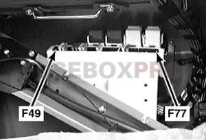

| No. | Amps | Assignment/Designation |
| 49 | 15A | Independent Heating Relay (IHKR) |
| 50 | 15A | Independent Park/Auxiliary Heating (IHKR), Independent Heating Receiver |
| 51 | 20A | Sunroof Module |
| 52 | 30A | Australia: Cigar Lighter Relay (Front Cigar Lighter) |
| 30A | except Australia: Front Cigar Lighter, Rear Cigar Lighter | |
| 53 | 20A | Rear Right Lumbar Support Switch, Rear Right Seat/Headrest Adjustment Switch, Rear Left Seat/Headrest Adjustment Switch, Rear Left Lumbar Support Switch, Rear Compartment Lumbar Support Motor (09.1995→) |
| 54 | 20A | 09.1997→: Trailer Socket |
| 55 | 7.5A | General Module |
| 56 | 7.5A | →09.1995: General Module |
| 7.5A | 09.1997→: Antitheft Horn (DWA) | |
| 57 | 15A | Fuel Pump Relay No.1 |
| 25A | Fuel Pump Relay No.1 | |
| 58 | 5A | Rear Lid Lock Switch, Tilt Sensor, Electrochromic Interior Rear View Mirror, Interior Protection Control Unit, ZV Tank Flap Relay |
| 59 | 30A | 1994→?: Rear Window Defogger Relay |
| 15A | ?: Cooler Box | |
| 60 | – | – |
| 61 | 20A | except 750iXL (09.1995→): Rear Compartment Blower Relay, Rear Compartment Blower Control Unit |
| 20A | 750iXL (09.1995→): Rear Compartment Blower Relay | |
| 62 | 5A | Electrochromic Interior Rear View Mirror |
| 63 | 15A | Left Rear Seat Heating Switch, Right Rear Seat Heating Switch |
| 64 | 5A | Parking Aid Control Unit, Distance Warning |
| 30A | CD Changer | |
| 65 | 15A | EDC Control Unit, Switching Centre, Front Right Acceleration Sensor (→09.1995), Rear Right Acceleration Sensor (→09.1995) |
| 66 | 5A | Cigar Lighter Relay |
| 67 | – | – |
| 68 | 5A | except 750iXL (09.1995→): Rear Compartment Blower Relay, Rear Compartment Blower Control Unit |
| 5A | 750iXL (09.1995→): Rear Compartment Heater/Air Conditioner | |
| 69 | 30A | Radio, Navigation Control Unit, GPS Receiver, Rear Cigar Lighter, CD Changer, Unloader Relay Terminal R, Video Module, On-Board Monitor, Rear Compartment Monitor, Amplifier |
| 70 | 10A | Transceiver/Charging Electronics (Motorola), Interface (Motorola), Compensator, Voice Input, Telephone – Basic Interface (Siemens, Nokia, Jbit), Eject Box (Siemens F), Rear Eject Box (Siemens F) |
| 71 | – | |
| 72 | – | |
| 73 | – | |
| 74 | – | |
| 75 | – | |
| 76 | 30A | Windscreen Defogger Relay No.1 |
| 77 | 30A | Windscreen Defogger Relay No.2 |
| & | ||
| 79 | 40A | Rear Window Defogger Relay |
| Relay | ||
| R1 | ||
| R2 | Independent Heating Relay | |
| R3 | USA: ZV Tank Flap Relay | |
| R4 | Unloader Relay Terminal 15 | |
| Unloader Relay Terminal R | ||
| R5 | Fuel Pump | |
| Rear Compartment Blower | ||
| R6 | Rear Window Defogger | |
Additional Fuses
- Engine Fuse Block (Petrol Engines):
M52 – 2.8L (Locaation: LHD / RHD)
M62 – 3.5L, 4.4L V8 (Location: LHD / RHD)
M73 – 5.4L V12 (Location: LHD / RHD) - Diesel Engines:
M51 – 2.5L (Location)
M57 – 2.9L (Location)
M67 – 3.9L V8 (Location)
| No. | Amps | Assignment/Designation |
| 1 | 30A | M51, M57: Digital Diesel Electronics (DDE) Control Unit, AGS Transmission Control Unit, Timed Valve, Injection Pump |
| 30A | M52: Digital Motor Electronics (DME) Control Unit, DME Relay, Diagnostic Connector, AGS Transmission Control Unit | |
| 30A | M52 (09.1998→): Digital Motor Electronics (DME) Control Unit, Diagnostic Connector, AGS Transmission Control Unit | |
| 30A | M67: Digital Diesel Electronics (DDE) Control Unit No.1 (Master) | |
| 30A | M62: Digital Motor Electronics (DME) Control Unit, AGS Transmission Control Unit, Hot-Film Air Mass Flow Sensor, Camshaft Hall Effect Sensor, Idle Actuator, Cooling Characteristic Map | |
| 30A | M73: Digital Motor Electronics (DME) Control Unit No.1 & 2, DME Relay No.1 & 2 (→05.1997), AGS Transmission Control Unit, Diagnostic Connector | |
| 2 | 30A | M51, M57: Glow Plug Relay, Temperature Switch E-Box, Engine Mount Electrical Changeover Valve, Changeover Valve for Exhaust Gas Recirculation (AGR), Hot-Film Air Mass Meter |
| 30A | M52: Digital Motor Electronics (DME) Control Unit, Hot-Film Air Mass Flow Sensor, Fuel Injectors No.: “1”, “2”, “3”, “4”, “5”, “6” | |
| 30A | M52 (09.1998→): Digital Motor Electronics (DME) Control Unit, Charcoal Filter Valve, Idle Actuator, Secondary Air Pump Valve, Fuel Injectors No.: “1”, “2”, “3”, “4”, “5”, “6”, Individual Control Intake System Valve, VANOS Intake Valve, VANOS Exhaust Valve | |
| 30A | M62 (→05.1997): Cooling Characteristic Map, Fuel Injector No.: “1”, “2”, “3”, “4”, “5”, “6”, “7”, “8” | |
| 30A | M62 (05.1997→): Secondary Air Pump Valve, Camshaft 2 Hall-Effect Sensor, VANOS Valve, Idle Actuator, Fuel Injector No.: “1”, “2”, “3”, “4”, “5”, “6”, “7”, “8” | |
| 30A | M67: Preheater Relay. Hot-Film Air Mass Meter, Rail Pressure Control Valve, Camshaft Hall-Effect Sensor, Supercharger Control Solenoid Valve, Changeover Valve for Exhaust Gas Recirculation (AGR), Engine Mount Electrical Changeover Valve | |
| 30A | M73 (→05.1997): Digital Motor Electronics (DME) Control Unit No.1, Oxygen Sensor after Catalytic Converter (→09.1995), Oxygen Sensor before Catalytic Converter (→09.1995), Hot-Film Air Mass Flow Sensor, Hall-Effect Sensor, Tank Ventilation Valve No.1, Fuel Injectors No.: “1”, “2”, “3”, “4”, “5”, “6” | |
| 30A | M73 (05.1997→): Digital Motor Electronics (DME) Control Unit No.1, EML Control Unit, Hot-Film Air Mass Flow Sensor, Hall-Effect Sensor, Tank Ventilation Valve No.1, Fuel Injectors No.: “1”, “2”, “3”, “4”, “5”, “6”, Air-Contained Fuel Injection Valves (Bank 1), AGS Transmission Control Unit (?), Camshaft Hall Sensor (?) | |
| 3 | 20A | M52: Oxygen Sensor before Catalytic Converter, Oxygen Sensor No.2 before Catalytic Converter |
| 30A | M52 (09.1998→): Crankshaft Sensor, Hot-Film Air Mass Meter, Camshaft Sensor No.1 & 2, Characteristic Map Cooling Thermostat | |
| 20A | M62: Heated Oxygen Sensor 1 in Front of Catalytic Converter, Heated Oxygen Sensor 2 in Front of Catalytic Converter, Heated Oxygen Sensor 1 behind Catalytic Converter (740iL USA), Heated Oxygen Sensor 2 behind Catalytic Converter (740iL USA) | |
| 20A | M73 (09.1995-01.1996): Oxygen Sensor after Catalytic Converter, Oxygen Sensor No.2 after Catalytic Converter, Oxygen Sensor before Catalytic Converter, Oxygen Sensor No.2 before Catalytic Converter | |
| 4 | 30A | M52: Digital Motor Electronics (DME) Control Unit, Idle Actuator, AGS Transmission Control Unit, VANOS Intake Valve, Fuel Tank Vent Valve |
| 30A | M52 (09.1998→): Oxygen Sensor after Catalytic Converter, Oxygen Sensor No.2 after Catalytic Converter, Oxygen Sensor before Catalytic Converter, Oxygen Sensor No.2 before Catalytic Converter, AGS Transmission Control Unit | |
| 30A | M62: Digital Motor Electronics (DME) Control Unit, DME Relay (→04.1997), Diagnostic Connector, AGS Transmission Control Unit | |
| 30A | M67: AGS Transmission Control Unit, Hot-Film Air Mass Meter, Changeover Valve for Exhaust Gas Recirculation 2 (EGR), Changeover Valve for Exhaust Gas Recirculation (AGR) | |
| 30A | M73: ? | |
| 5 | 30A | M51, M57: AGS Transmission Control Unit, Fuel Heater, Diagnostic Connector |
| 30A | M52: Digital Motor Electronics (DME) Control Unit, Ignition Coils No.: “1”, “2”, “3”, “4”, “5”, “6” | |
| 30A | M52 (09.1998→): Unloader Relay Terminal 15 (Ignition Coils No.: “1”, “2”, “3”, “4”, “5”, “6”) | |
| 30A | M67: Digital Diesel Electronics (DDE) Control Unit No.2 (Slave), Rail Pressure Control Valve, Camshaft Hall-Effect Sensor | |
| 30A | M62 (→05.1997): Ignition Coils No.: “1”, “2”, “3”, “4”, “5”, “6”, “7”, “8” | |
| 30A | M62 (05.1997→): Unloader Relay Terminal 15 (Ignition Coils No.: “1”, “2”, “3”, “4”, “5”, “6”, “7”, “8”) | |
| 30A | M73: Ignition Coils | |
| 78 | 40A | (Location: M60 (LHD) / M60 (RHD)) Auxiliary Fan Stage 2 Relay (01.1995-09.1995) |
| 50A | (Location: M73 (LHD) / M73 (RHD)) Electric Fan (→09.1995) | |
| 50A | (Location) Electric Fan (09.1995→) | |
| 80 | 40A | Rear Lid Module |
| 81 | 40A | (Location) Heating Blower Relay (09.1996→) |
| Officials Utility Vehicle | ||
| 001 | 80A | Fuse No.: “01P, “02P” |
| 01P | 50A | Window Heating Control Unit |
| 02P | 50A | Window Heating Control Unit |
Passenger Compartment Fuse Box No.2 (only RHD)
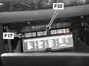

| No. | Amps | Assignment/Designation |
| 1 | – | – |
| 2 | – | – |
| 3 | 30A | Wiper Relay |
| 4 | 30A | Headlight Washer Module |
| 5 | 15A | Horn Relay |
| 6 | 20A | General Module |
| 7 | 7.5A | Water Valves, Auxiliary Water Pump, Independent Heating Receiver, Radio Clock Receiver, Front Shutoff Valve (750iXL) |
| 8 | 30A | Passenger’s Door Module |
| 9 | 20A | Auxiliary Fan Stage 1 Relay |
| 10 | 5A | Visual Entry Aid Relay |
| 25A | 1994→?: ABS/ASC Control Unit | |
| 11 | 15A | Heating and A/C Control Module |
| 30A | 1994→01.1995 (without Memory): Front Passenger’s Seat Adjustment Switch, Passenger’s Back-Rest Adjustment Switch, Switch for Passenger’s Seat Thigh Support, Passenger’s Seat Lumbar Support Switch | |
| 30A | 1994→01.1995 (with Memory): Front Passenger’s Active Seat Control Unit, Passenger’s Seat Movement Motor, Passenger’s Seat Height Adjustment Motor, Passenger’s Seat Cushion Tilt Motor, Passenger’s Backrest Recliner Motor, Passenger’s Seat Memory Control Unit, Passenger’s Back-Rest Actuator Motor, Passenger’s Headrest Motor | |
| 12 | 15A | 01.1995-09.1995: Steering Column Adjustment Control Unit |
| 13 | 20A | 1994→01.1995: Steering Column Adjustment Control Unit |
| 14 | 10A | 1994→01.1995: Rear Headrest Control Unit |
| 5A | Left B-Pillar Light, Right B-Pillar Light, B-Pillar Lights Relay | |
| 15 | 30A | Steering Column Inclination Motor, Steering Column Adjustment Motor, Driver’s Seat Movement Motor, Driver’s Seat Height Adjustment Motor, Driver’s Seat Cushion Tilt Motor, Driver’s Backrest Recliner Motor, Driver’s Headrest Motor, Seat/Steering Column Memory (SM/LSM) Control Unit, Driver’s Thigh Support Motor, Driver’s Back-Rest Actuator Motor, Driver’s Seat Lumbar Support Switch, Driver’s Active Seat Control Unit |
| 16 | 10A | 1994→01.1995: Sunshade Control Unit, Sunshade Switch |
| 30A | 01.1995→ (without Memory): Front Passenger’s Seat Adjustment Switch, Passenger’s Back-Rest Adjustment Switch, Switch for Passenger’s Seat Thigh Support, Passenger’s Seat Lumbar Support Switch | |
| 30A | 01.1995→ (with Memory): Front Passenger’s Active Seat Control Unit, Passenger’s Seat Movement Motor, Passenger’s Seat Height Adjustment Motor, Passenger’s Seat Cushion Tilt Motor, Passenger’s Backrest Recliner Motor, Passenger’s Seat Memory Control Unit, Passenger’s Back-Rest Actuator Motor, Passenger’s Headrest Motor | |
| 17 | 10A | Fuel Pump Relay No.1, Switching Centre, ABS/ASC Control Unit, Steering Angle Sensor, Active Cruise Control (ACC) Control Unit, Charcoal Filter Valve, Fuel Changeover Circuit, Leakage Diagnosis Pump, Secondary Air Pump Relay, Control Unit for Electrically Heated Catalytic Converter |
| 10A | M51, M52, M60: ASC/DSC System Switch, Starter Relay (M60 – 1994-01.1995), Fuel Pump Relay, ABS/ASC Control Unit, Secondary Air Pump Relay (M60, M73) | |
| 10A | M73: ASC/DSC System Switch, Fuel Pump Relay, ABS/ASC/DSC Control Unit, Secondary Air Pump Relay, Air Pump Relay(09.1996→), Steering Angle Sensor (with DSC), Fuel Changeover Circuit (05.1997→), Leakage Diagnosis Pump (05.1997→) | |
| 10A | M62: ASC/DSC System Switch, Fuel Pump Relay, ABS/ASC/DSC Control Unit, Fuel Changeover Circuit, Leakage Diagnosis Pump, Charcoal Filter Valve, Steering Angle Sensor (with DSC) | |
| 18 | 5A | Instrument Cluster – Integrated Electronic Control Unit (IKE) |
| 19 | 5A | Unloader Relay Terminal 15 |
| 20 | 5A | Left Headlight (?→), Right Headlight (?→), Rear Window Defogger Relay, Heated Front Screen/Washer Jets Relay, Auxiliary Fan Stage 1 Relay, Auxiliary Fan Stage 2 Relay (09.1995→), Heating and A/C Control Module |
| 21 | 5A | Closed-Circuit Current Cutout Relay, Garage Door Opener (09.1995→), Control Unit for Electronic Battery Disconnecting Switch (03.2000→), Active Cruise Control (ACC) Control Unit (03.2000→) |
| 22 | 10A | M51, M57: Diagnostic Connector, Alternator, Fuel Heater, Oil Level Sensor, Gear Position Switch |
| 10A | M67: Diagnostic Connector, Alternator, AGS Transmission Control Unit, Temperature Switch, Oil Level Sensor | |
| 10A | M60: Diagnostic Connector, Oxygen Sensor Relay, Oil Leve Sensor, Temperature Switch, Gear Position Switch | |
| 10A | M52: Diagnostic Connector, Alternator, Temperature Switch, Oil Level Sensor, Gear Position Switch | |
| 10A | M52, M62, M73: Diagnostic Connector, Alternator, Temperature Switch, Oil Level Sensor, Gear Position Switch (except M62 – 09.1997→), AGS Transmission Control Unit (only M62 – 09.1997→) | |
| 23 | 5A | Instrument Cluster, Light Module, RDC Control Unit (03.1998→), DWS Control Unit, ZV Tank Flap Relay, Auxiliary Fan Stage 3 Relay |
| 24 | 5A | M51, M57: Digital Diesel Electronics (DDE) Control Unit, DDE Control Unit Relay |
| 5A | M67: Digital Diesel Electronics (DDE) Control Unit No.1 (Master) | |
| 5A | M52, M62: Digital Motor Electronics (DME) Control Unit | |
| 5A | M60: Digital Motor Electronics (DME) Control Unit, Unloader Relay Terminal 15 (→09.1995) | |
| 5A | M73: Digital Motor Electronics (DME) Control Unit No.1 & 2, Unloader Relay Terminal 15 (→09.1995) | |
| 25 | – | – |
| 26 | 5A | Integrated Electronic Control Unit (IKE), Gong, Instrument Cluster, Gear Indicator Light, Automatic Diagnostics Control Unit (→09.1995), Electronic Immobilizer Control Unit (EWS – 01.1995→), Steering Angle Sensor (with DSC – 09.1996→) |
| 27 | 5A | OBD2 Socket (09.1995→ (except 750iXL)), Multi-Information Display (MID), Multi-Information Display (MID) Rear Passenger Compartment, Passenger’s Seat Adjustment Remote Control Switch |
| 28 | 5A | Wiper Relay No.1 & No.2, Central Lock Remote Control (01.1995→09.1995), LED Display DWA (01.1995-02.1998), Solar Sensor with DWA LED (03.1999→), Antenna Amplifier (Central Lock – 09.1995→), Relay for Rear Lid Motor (09.1997→), RDC Control Unit (09.1997→) |
| 29 | 30A | General Module |
| 30 | 10A | Heated Front Screen/Washer Jets Relay |
| 31 | 30A | Driver’s Door Lock Switch, Driver’s Door Module, Driver’s Door Switch Block (→09.1995) |
| 32 | 30A | →08.1996: Heating Blower Relay |
Passenger Compartment Fuse Box No.3 (only RHD)
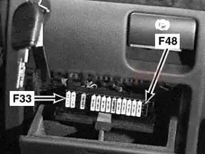

| No. | Amps | Assignment/Designation |
| 33 | 25A | ABS/ASC Control Unit (Valve Relay) |
| 34 | 30A | →08.1995: Auxiliary Fan Stage 2 Relay |
| AGS Transmission Control Unit, Diagnostic Connector | ||
| 35 | – | – |
| 36 | 10A | Coil Spring |
| 37 | – | – |
| 38 | 5A | →09.1995: Auxiliary Fan Stage 2 Relay |
| 5A | 01.1995→: Auxiliary Fan Stage 3 Relay | |
| 39 | 25A | Switching Centre |
| 15A | Driver’s Seat Heating Switch, Passenger’s Seat Heating Switch | |
| 40 | 5A | Diagnostic Connector |
| 41 | 5A | Horn Relay, Rain Sensor (01.1996→), Gear Indicator Light, General Module, Integrated Electronic Control Unit (→09.1997), Remote Control Central Locking (→09.1995) |
| 42 | 7.5A | Charge Socket, Driver’s Make-Up Mirror Light, Passenger’s Make-Up Mirror Light, Passenger’s Seat Parcel Shelf Light, Driver’s Seat Parcel Shelf Light |
| 43 | 5A | Left Front Airbag Sensor (01.1996-02.1999), Right Front Airbag Sensor (01.1996-02.1999), Driver’s Seat Belt Buckle Switch (03.1997-03.1999),, Passenger’s Seat Belt Buckle Switch (03.1997-09.1998), Electronic Seat Control, Integrated Electronic Control Unit (09.1997→), Instrument Cluster (→09.1997) |
| 44 | 5A | Brake Light Switch, Light Module (09.1997→), Electronic Immobilizer (EWS) Control Unit (01.1995-), Clutch Switch (09.1997→), Cruise Control Module (→08.1996) |
| 45 | 5A | Airbag Diagnostic Module |
| 46 | 5A | Unloader Relay Terminal R, Diversity, Navigation Control Unit, Transceiver/Charging Electronics, Interface, Voice Input, DSP Operating Unit, Telephone – Basic Interface, On-Board Monitor, GPS Receiver |
| 47 | 5A | Multi-Information Display (MID) Rear Passenger Compartment, Multifunction Steering Wheel (Coil Spring), Multi-Information Display (MID) |
| 48 | 10A | Switching Centre, Rear Headrest Control Unit, Sunshade |
Luggage Compartment Fuse Box No.2
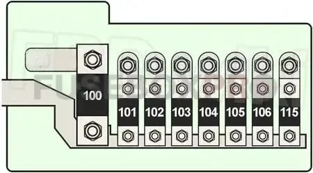
| No. | Amps | Assignment/Designation |
| 100 | 200A | Fuse No.: “107”, “108”, “109”, “110”, “111”, “112”, “113”, “114” |
| 101 | 80A | Fuse No.: “49”, “50”, “51”, “52”, “53”, “54 (09.1998→)”, “80 (09.1998→)” |
| 102 | 80A | Fuse No.: “55”, “56”, “57”, “58”, “59”, “60 (09.1998→)”, “61 (09.1998→)”, “79 (01.1996→)” |
| 103 | 80A | M51, M57: Digital Diesel Electronics (DDE) Relay |
| 80A | M67: Digital Diesel Electronics (DDE) Relay No.1 & 2 | |
| 50A | Trailer Module (AHM) | |
| 104 | 50A | Unloader Relay Terminal 15 |
| 105 | 80A | →09.1998: Fuse No.: “69”, “70” |
| 80A | 09.1998→: Fuse No.: “78” | |
| 100A | M57: Preheater Relay, Fuse No.: “78” | |
| 100A | M67: Preheater Relay, Glow Plug Relay, Fuse No.: “78” | |
| 100A | M51 (09.1998→): Glow Plug Relay, Auxiliary Fan Relay (Stage 3) | |
| 106 | 80A | 09.1998→: Fuse No.: “69”, “70” |
| 80A | →09.1998: Auxiliary Fan Relay (Stage 2) | |
| 80A | M51 (→09.1998): Auxiliary Fan Relay (Stage 3), Glow Plug Relay | |
| 115 | 50A | Trailer Module (AHM) |
| 50A | 09.1997→: Rear Lid Module | |
| 010 | 250A | (Location) System Battery, Fuse No.: “100” |
Fusible Link Block
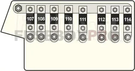
| No. | Amps | Assignment/Designation |
| 107 | 50A | Secondary Air Pump Relay, Air Pump Relay (M73) |
| 108 | 50A | Motor Relay |
| 50A | ABS/ASC Control Unit | |
| 109 | 80A | M51: Digital Diesel Electronics (DDE) Relay, Fuse No.: “5” (Engine Fuse Holder) |
| 80A | M52: Digital Motor Electronics (DME) Relay, Fuse No.: “1” (Engine Fuse Holder) | |
| 80A | M60: Digital Diesel Electronics (DDE) Control Unit, AGS Transmission Control Unit, DME Relay, Diagnostic Connector | |
| 80A | M73 (→09.1995): Digital Motor Electronics (DME) Relay No.1 & 2, DME Control Unit No.1 & 2, AGS Transmission Control Unit, Diagnostic Connector | |
| 80A | M73 (09.1995→): Digital Motor Electronics (DME) Relay No.1 & 2, Fuse No. “1” (Engine Fuse Holder), Unloader Relay 15 Terminal (05.1997→) | |
| 80A | M62 (→05.1997): Digital Motor Electronics (DME) Relay, Fuse No.: “1” (Engine Fuse Holder) | |
| 80A | M62 (05.1997→): Digital Motor Electronics (DME) Relay, Fuse No.: “4”, “5” (Engine Fuse Holder) | |
| 110 | 80A | Fuse No.: “3”, “4”, “5”, “6”, “7”, “8”, “9”, “10”, “11”, “12 (09.1995→)”, “26”, “27”, “28” |
| 111 | 50A | Ignition Switch, Fuse No.: “39 (→09.1998)” |
| 112 | 80A | Light Module, Fuse No.: “33”, “34 (except 01.1995-09.1995)”, “78 (01.1995-09.1995)” |
| 113 | 80A | Light Module, Closed-Circuit Current Cutout Relay, Fuse No.: “29”, “30”, “31”, “32”, “81 (→09.1996)” |
| 80A | →09.1996 (except Closed-Circuit Current Cutout Relay): Light Module, Fuse No.: “12 (→03.1996)”, “13 (→03.1996)”, “14 (→03.1996)”, “15”, “16”, “29”, “30”, “31”, “32” | |
| 80A | 09.1996→ (except Closed-Circuit Current Cutout Relay): Light Module, Fuse No.: “15”, “16”, “17 (M51)”, “29”, “30”, “31”, “32”, “81” | |
| 114 | 50A | →01.1995: Ignition Switch, Unloader Relay 15 Terminal, Starter Relay |
| 50A | M73 (01.1995-09.1995): Ignition Switch, Unloader Relay 15 Terminal, Electronic Immobilizer (EWS) Control Unit | |
| 50A | M73, M62 (09.1995→): Ignition Switch, Electronic Immobilizer (EWS) Control Unit | |
| 50A | 09.1995→: Ignition Switch |
Relay Location
- →01.1995 (M60, M73): Starter Relay (K1 – Location: LHD (Under LH Side of Dash) / RHD (Under RH Side of Dash))
- Horn Relay (K2 – Location: LHD (Under LH Side of Dash) / RHD (Behind Glove Compartment))
- 1994→?: Unloader Relay Terminal R (K3 – Location (Luggage Compartment))
- Blower Relay (K4 – Location: LHD (Behind Glove Compartment) / RHD (Driver’s Side Footwell))
- Headlight Washer Module (K6 – Location: LHD (Behind Glove Compartment) / RHD (Engine Compartment))
- Unloader Relay Terminal 15 (K9 – Location: LHD (Behind Glove Compartment) / RHD (Behind Glove Compartment))
- 09.1998→: Wiper Relay (K11 – Location: LHD (Engine Compartment))
- Auxiliary Fan Stage 1 Relay (Location: LHD (Behind Glove Compartment) / RHD (Driver’s Side Footwell))
- Auxiliary Fan Stage 2 Relay (Location: LHD (Behind Glove Compartment) / RHD (Driver’s Side Footwell))
- Wiper Relay No.1 (K36 – Location (Engine Compartment): LHD / LHD M73 / RHD)
- Wiper Relay No.2 (K37 – Location (Engine Compartment): LHD / LHD M73 / RHD))
- Closed-Circuit Current Cutout Relay (K72 – Location: LHD (Behind Glove Compartment) / RHD (Behind Glove Compartment))
- →09.1998: ABS Motor Relay (K94 – Location (Engine Compartment): LHD / LHD M73 / RHD)
- →09.1998: ABS Valve Relay (K95 – Location: LHD (Behind Glove Compartment) / RHD (Engine Compartment))
- M73: Air Pump Relay (K118 – Location (Engine Compartment): LHD / RHD)
- 750iXL: Rear Compartment Air Conditioning Water Valve Relay (K127 – Location)
- 09.1997→: Rear Lid Motor Relay (K128 – Location (Behind Glove Compartment))
- 09.1998→: Visual Entry Aid Relay (K131 – Location (Behind Glove Compartment))
- Heated Front Screen/Washer Jets Relay (K198 – Location (Behind Glove Compartment): LHD / RHD)
- 09.1995→: Auxiliary Fan Stage 3 Relay (K201 – Location (Behind Glove Compartment))
- Diesel: Glow Plug Relay (K2000 – Location (Engine Compartment): M51 / except M51)
- Diesel: Digital Diesel Electronics (DDE) Relay (K2003 – Location (Engine Compartment): M51)
- Diesel: Preheater Relay (K2283 – Location (Engine Compartment))
- M67: Digital Diesel Electronics (DDE) Relay No.1 (K2317 – Location (Engine Compartment))
- M67: Digital Diesel Electronics (DDE) Relay No.2 (K2318 – Location (Engine Compartment))
- Digital Motor Electronics (DME) Relay (K6300 – Location: M52 LHD / M52 RHD / M60 LHD / M60 RHD / M62 LHD / M62 RHD)
- M52, M60, M62: Oxygen Sensor Relay (K6303 – Location (Engine Compartment): LHD / RHD)
- except Diesel: Secondary Air Pump Relay (K6304 – Location (Engine Compartment): LHD / RHD)
- M73: Digital Motor Electronics (DME) Relay No.1 (K6310 – Location (Engine Compartment) LHD →05.1997 / LHD 05.1997→ / RHD)
- M73: Digital Motor Electronics (DME) Relay No.2 (K6320 – Location (Engine Compartment) LHD →05.1997 / LHD 05.1997→ / RHD)
- Start Relay (K6324 – Location: LHD →05.97 / RHD / LHD M62 05.97→ / LHD M73 05.97→)
- 05.1997→: Unloader Relay Terminal 15 (K6326 – Location (Engine Compartment): M62 LHD / M73 LHD)
In conclusion, the BMW 7-Series E38 is a luxurious car that comes equipped with various electrical components, such as the fuse box and relay, to ensure a comfortable and high-performance ride. Regular maintenance and replacement of faulty electrical components, such as fuses and relays, are essential to ensure the smooth running of the car. Understanding the location and function of these electrical components is vital in maintaining the integrity of the electrical system and preventing any electrical damage to the car.
Leave a Reply