Mercedes-Benz Vito W638 fuse box and relay (1995-2003)
The Mercedes-Benz Vito W638, which is built in 1995, 1996, 1997, 1998, 1999, 2000, 2001, 2002, and 2003 with both gasoline and diesel engines, is the first generation of the Mercedes Vito lineup. The model has undergone styling changes during this time. You can find a description of the fuse and relay for the Mercedes Vito 638 in this publication, along with box diagrams and visual examples of where they are located. Decide which fuse controls the cigarette lighter.

Depending on the year of production and the quality of the electrical equipment, the way the boxes are made and what the parts inside them are used for may be different from what is shown.
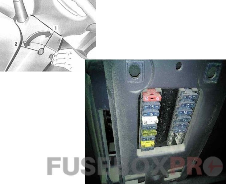
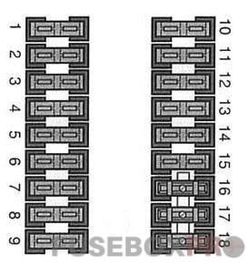
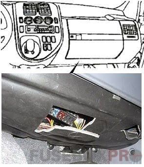
The box under the steering wheel
Diagram
Assignment
|
1 |
10/15A |
Right marker lights, power circuit 58 relay K71, trailer connector X18 |
|
2 |
10/15A |
Right high beam, X146 connector |
|
3 |
10/15A |
Left high beam, high beam indicator, fog lamp relay 1 K88 (DRL system), connector X146 |
|
4 |
15A |
Convenience locking system control unit, horn relay, reverse lamp limit switch (manual transmission), automatic transmission selector position switch (sensor), Cruise control button (M111) |
|
5 |
15A |
Stop light sensor, Cruise control button, transmission failure indicator (M104.900) |
|
6 |
20A |
Wiper, rear wiper, alarm |
|
7 |
10/15A |
External lighting lamp failure control unit, heat exchanger (M611), tachograph, diagnostic connector, glove box illumination lamps, speed sensor (M104.900), cabin air recirculation switch, fluid level indicator in the washer reservoir, indicator lamp and ADS/ABD system display, ABS/ETS indicator |
|
8 |
20A |
Navigation system processor, cigarette lighter, interior lamp, sliding door lamp, automatic antenna, radio, trunk connector |
|
9 |
10/15A |
Direction indicators (alarms), instrument cluster, tachograph, clock |
|
10 |
7.5/15A |
Instrument cluster illumination, license plate lighting, daytime running lights, car radio or receiver, air conditioning control unit illumination lamps, automatic transmission selector illumination lamp, cigarette lighter lamp, license plate lamps, windshield wiper relay K19 winding unit -headlights, relay for switching on the front fog lamps K88 / K89 (only with DRL), tachograph, instrument cluster, backlight lamps for buttons and switches |
|
11 |
10/15A |
Left position lights, license plate lights, circuit 58 of relay K71, trailer connector |
|
12 |
15A |
Right low beam, rear fog lamp, DRL system relay, front and rear fog lamp switch illumination lamp |
|
13 |
15A |
Left low beam, DRL system relay |
|
14 |
15A |
Front and rear fog light switch, front fog light switch |
|
15 |
15A |
Car radio or radio, navigation processor, airbags |
|
16 |
Not used |
|
|
17 |
Not used |
|
|
18 |
Not used |
For the cigarette lighter, fuse number 8 is responsible for 20A.
Two relays are installed on the side of the block. Left – Turn Signal Relay, Right – Wiper Relay.
For more information about the power supply circuits of the windshield wipers (front and rear) in the Mercedes Vito 638, you can find it here: “download wiring diagram“.
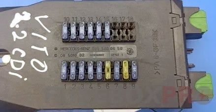
The box under the glove box
The second fuse box is located at the bottom of the panel, in the passenger’s footwell, under the glove compartment.
Diagram
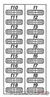
Designation
|
1 |
7.5A |
Body side window vents |
|
2 |
30A |
Right door power window and front sliding sunroof, front sliding sunroof position switch, central power window switch (driver’s door), passenger’s door power window switch |
|
3 |
30A |
Left door power window and rear sliding sunroof, rear sliding sunroof position switch, driver’s door power window switch |
|
4 |
25A |
Central locking control unit, lock actuators |
|
5 |
10A |
Left sun visor lamp, right sun visor lamp, left side lamps, right side lamps, rear lamps |
|
6 |
20A |
Power outlets |
|
7 |
7.5A |
GSM mobile phone unit, mobile phone handset |
|
8 |
20A |
Anti-theft control unit, anti-theft alarm button |
|
9 |
10A |
Auxiliary water heater relay |
|
10 |
7.5A/10A |
Anti-theft Siren (ATA) |
|
11 |
7.5A |
Anti-theft system control unit, additional direction indicator control unit (left turn signal), special signals control unit (left turn signal), anti-theft system control unit (ATA 2), left turn signal lamp, left front turn signal lamp, left rear turn signal, left side turn signal relay, left turn indicator lamp |
|
12 |
7.5A |
Anti-theft system control unit, additional direction indicator control unit (right turn signal), special signal control unit A44 (right turn signal), anti-theft system control unit (ATA 2), right turn signal lamp, right front turn signal lamp, lamp right rear turn signal, right side turn signal relay, right turn indicator lamp |
|
13 |
7.5/15/20A |
Anti-theft system control unit (ATA 2) |
|
14 |
7.5A |
Anti-theft system control unit (ATA 2) |
|
15 |
7.5A |
Front ultrasonic sensor (ATA2), rear ultrasonic sensor (ATA2), anti-theft siren (ATA 2) H18 |
|
16 |
Not used |
|
|
17 |
Not used |
|
|
18 |
Not used |
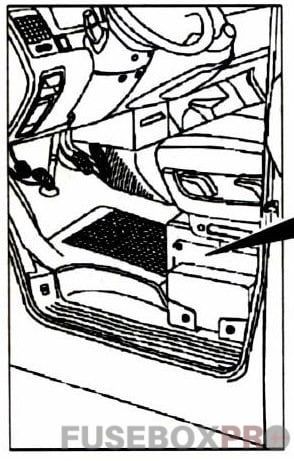
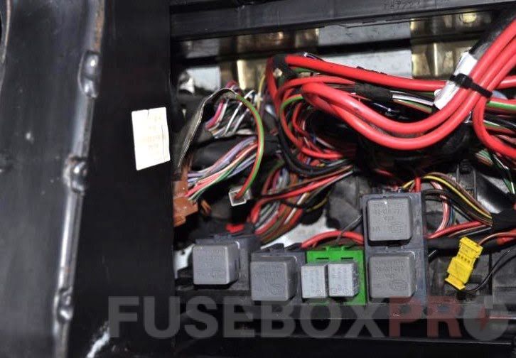
The box under the driver’s seat
On the side, under the driver’s seat, there are 2 separate boxes with fuses and relays.
Fuse box
Photo example
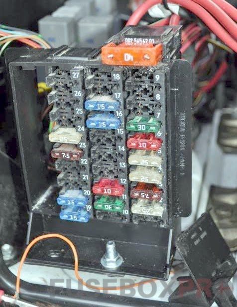
Diagram
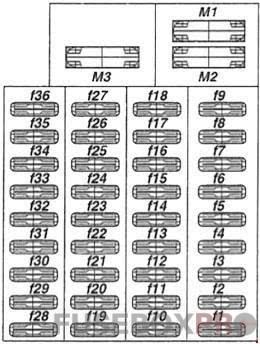
Appointment
|
1 |
7.5/10A |
Electronic control unit ABS, ASR, EBV, air suspension control unit |
|
2 |
25A |
Rear window wiper control relay combination (M111, M611) / Vehicle authorization system (DAS) control unit (M104) |
|
3 |
7.5A |
Radiator fan (M111 until 01.02.00) / Control unit for the vehicle control authorization system (DAS) (M111, M611) |
|
4 |
25A |
Radiator fan (petrol engine), charge air cooler (diesel engine) |
|
5 |
25A |
ABS electro-hydraulic unit (from 01.02.00) |
|
6 |
10A |
ETC control module, Vehicle Authorization System (DAS) control module / ME-SFI control module (M104) |
|
7 |
30A |
Heater control unit |
|
8 |
20A |
Headlight wiper relay |
|
9 |
7.5A |
Additional heater control unit / ASR mode switch (M111, M611 from 01.02.00) |
|
10 |
25A |
Socket trailer, refrigerator |
|
11 |
30A |
Rear wiper combination relay, towing protection device (EDW/ZV), left side turn signal relay, right side turn signal relay |
|
12 |
10A |
Air conditioner control unit |
|
13 |
30A |
Air suspension compressor relay |
|
14 |
7.5A |
Air suspension control unit, tachograph, auxiliary light, stationary water heater control unit, turn signal auxiliary control unit |
|
15 |
7.5A |
Radio power supply |
|
16 |
15A |
Heating control unit, taxi console |
|
17 |
15A |
Automatic transmission control unit, automatic transmission gear selector, automatic transmission program selection button (M111 from 02/01/00 and M611), automatic transmission mode switch (M111 until 02/01/00), automatic transmission selector position switch (sensor) |
|
18 |
10A |
Anti-theft control unit, GSM mobile phone unit, handset unit, driver’s door mirror adjuster, passenger’s door mirror adjuster, heated exterior mirrors, mirror adjustment switch block |
|
19 |
15A |
Starter Interlock Relay (M111), Fuel Pump Relay (M111), Radiator Fan Motor (M111), Fluid Pump Relay (M611), Breather Heater (M611) |
|
20 |
15A |
Terminal 15 (petrol engines) |
|
21 |
15A |
Ignition coil supply (petrol engine) |
|
22 |
20A |
Fuel pump (petrol engine) |
|
23 |
7.5A |
Diesel engine control unit |
|
24 |
25A |
Diesel engine control unit |
|
25 |
10A |
Stationary water heater relay |
|
26 |
25A |
Heater control unit (diesel engine), non-volatile heater power supply (engine stopped operation) |
|
27 |
25A |
Additional heater control unit |
|
28 |
15A |
Relay supply circuit D+, fog lamp relay (DRL) |
|
29 |
10A |
DRL system relay (daytime running lights) |
|
30 |
10A |
DRL system relay (daytime running lights) |
|
31 |
10A |
Power circuit relay 58 |
|
32 |
30A |
Heated and seat adjustment circuit, left |
|
33 |
25A |
Right seat heating and adjustment circuit |
|
34 |
7.5A |
Water separator |
|
35 |
7.5A |
Rear air conditioner |
|
36 |
15A |
Rear air conditioner |
|
M1 |
40A |
Engine cooling fan unit 250W |
|
M1 |
60A |
Engine cooling fan assembly 500W |
|
М2 |
50/60A |
ABS hydraulic unit pump |
|
М3 |
40A |
Secondary air blower (petrol engine) |
Relay box
The photo
Diagram
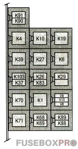
Decoding
|
К91 |
Right side turn signal relay (central locking system with remote control) |
|
К90 |
Left Turn Signal Relay (Central locking system with remote control) |
|
К4 |
Power circuit relay 15 (steering column lock 2) |
|
К10 |
Air Suspension Compressor Relay |
|
К19 |
Relay for the headlight glass cleaning system |
|
К39 |
Fuel pump relay |
|
К27 |
Passenger presence recognition relay (Seat unloaded relay) |
|
К6 |
Engine control unit relay |
|
К103 |
Relay for booster pump of the engine cooling system |
|
К37 |
Horn relay (horn) |
|
К26 |
Power supply relay D (steering column lock 3) |
|
К83 |
Fog Lamp Relay |
|
К29 |
Stationary heater relay(ZHE) |
|
К70 |
Power circuit relay 15 (special equipment) |
|
К1 |
Starter lock relay |
|
V9 |
Anti-theft diode ATA 1 |
|
V10 |
Anti-theft diode ATA 2 |
|
V8 |
Diode booster pump stationary heater |
|
K71 |
Power relay 58 |
|
K68 |
DRL system relay |
|
K69 |
DRL system relay |
|
K88 |
Fog lamp relay 1 (with DRL system) |
|
K89 |
Fog lamp relay 2 (with DRL system) |
Preglow relay
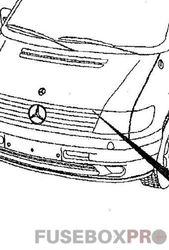
Separately, under the hood, additional relays can be installed, such as a preheat relay.
That’s all. And if you have something to add – write in the comments.