Mercedes-Benz Sprinter W906/NCV3 Fuse Box & Relay (2006-2017)

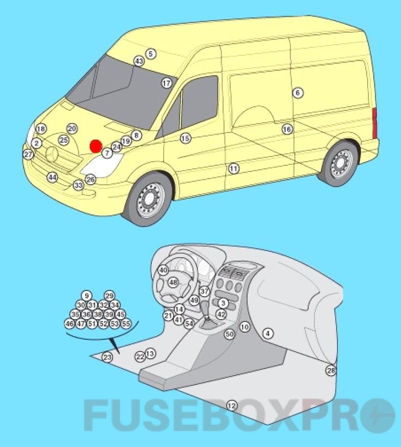
The Mercedes-Benz Sprinter 906 is the second generation of the Mercedes Sprinter line. Years of production: 2006, 2007, 2008, 2009, 2010, 2011, 2012, 2013, 2014, 2015, 2016, and 2017. In this material, you will find information about the locations of electronic control units, a description of the fuses and relays in the Mercedes Sprinter 906 with box diagrams, and photo examples of their performance. Select the fuses responsible for the cigarette lighter.

The execution of the boxes and the purpose of the elements in them may differ from those presented and depend on the year of manufacture, equipment level and region of delivery.
Layout
General block layout
Assignment
|
№ |
Fuse Function |
|
1 |
ABS electronic control unit |
|
2 |
A/C condenser fan motor relay |
|
3 |
Electronic air conditioning control unit – in the heater control panel |
|
4 |
A/C/Heater Fan Motor Control Module – Next to the fan motor |
|
5 |
Antenna signal booster |
|
6 |
Air suspension control unit – pillar “0” |
|
7 |
Anti-theft siren – engine compartment, left side |
|
8 |
Additional battery – engine compartment, left side |
|
9 |
Secondary Battery Relay |
|
10 |
Additional heater control unit (type 1) |
|
11 |
Additional heater control unit (type 2) |
|
12 |
Additional heater control unit (type Z) – in the heater unit |
|
13 |
Accumulator battery |
|
14 |
Diagnostic connector (DLC) |
|
15 |
Door electrical control unit, driver’s side |
|
16 |
Left rear door electrical control unit |
|
17 |
Control unit for electrical equipment of the right rear door |
|
18 |
ECM (Diesel) – Engine 651 |
|
19 |
ECM (Diesel) – except 651 engine |
|
20 |
Electronic engine control unit (gasoline) – on the engine |
|
21 |
Fuse/Relay Box, Instrument Panel |
|
22 |
Fuse/Relay Box, Footwell |
|
23 |
Fuse/Relay Box, Under Seat |
|
24 |
Glow Plug Control Unit – Engine 646 |
|
25 |
Glow plug control unit – except engine 646 |
|
26 |
Headlight control unit, left (xenon headlights) |
|
27 |
Headlight control unit, right (xenon headlights) |
|
28 |
Headlight range control unit – pillar “A” |
|
29 |
Rear defroster relay 1 |
|
30 |
Rear defroster relay 2 (with anti-theft system) |
|
31 |
Windshield defroster relay |
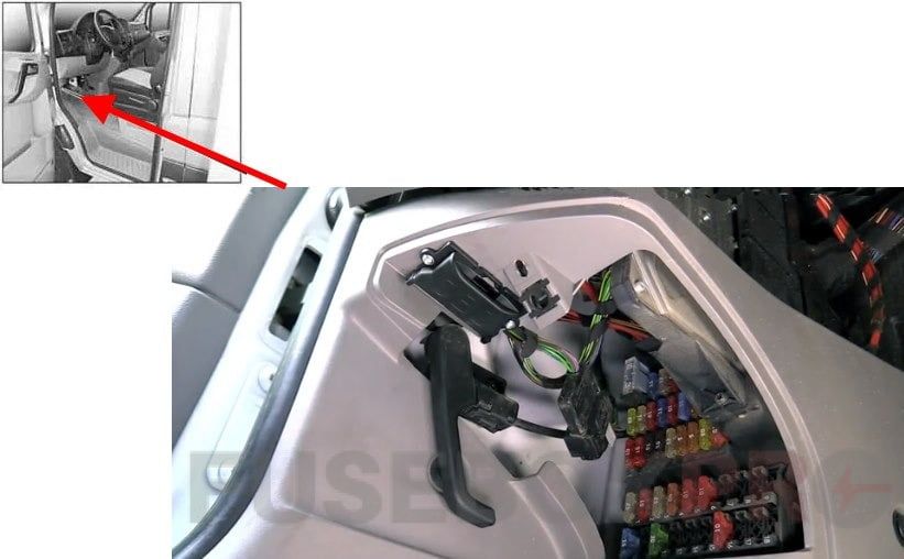
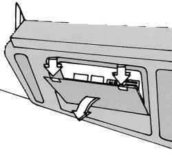
Fuse box and relay under the panel
Under the instrument panel, in the foot well on the left side of the vehicle, behind a protective cover is the main fuse and relay box. To access, turn the fastener in the middle of the cover.
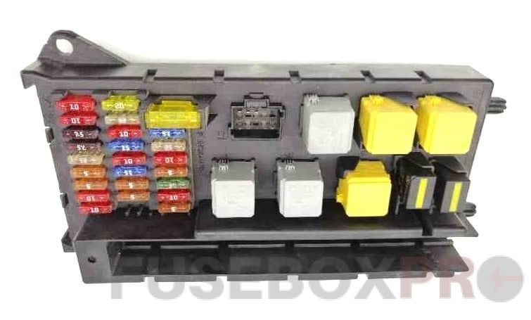
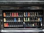
Photo
Diagram
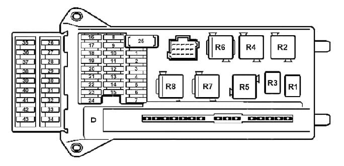
Designation
|
№ |
Amp |
Fuse Function |
|
1 |
15A |
Horn |
|
2 |
25A |
Steering column lock (ELV), electronic ignition and starter switch (EZS) |
|
3 |
10A |
Terminal 30z (petrol engines), electronic ignition and starter switch (EZS), instrument cluster |
|
4 |
5A |
Light switch (LDS), center console switch box (OBF; terminal 30) |
|
5 |
30A |
Front wiper |
|
6 |
15A Fuel pump |
|
|
10A Engine control, terminal 87 (5) (vehicles with code MI6/XM0) |
||
|
7 |
5A |
Steering column tube module (MRM) |
|
8 |
20A |
Motor control, terminal 87 (2) |
|
9 |
20A Engine control terminal 87 (3) (petrol vehicles) |
|
|
25A Engine control, terminal 87 (3) (vehicles with diesel engine) |
||
|
20A Engine control, terminal 87 (1) (vehicles with code MI6/XM0) |
||
|
10 |
10A |
Motor control terminal 87 (4) |
|
11 |
15A |
Terminal 15R |
|
12 |
10A |
Airbag terminal 15R |
|
13 |
15A |
Audio module, cigarette lighter, glove box lighting, bodybuilder tail lift, PND power socket (mobile navigation system) |
|
14 |
5A |
Light switch (LDS), instrument cluster, diagnostic socket, reversing warning lamp deactivation, anti-theft system with vehicle tracking, terminal 15 |
|
15 |
5A |
Headlight range adjustment (LWR), front heating system |
|
16 |
10A |
Motor control terminal 87 (1) |
|
17 |
10A |
Airbag |
|
18 |
7.5A |
Terminal 15, brake light switch |
|
19 |
7.5A |
Interior lighting, terminal 30 |
|
20 |
25A |
Terminal 30, right front power window, signal recording and excitation module |
|
21 |
5A |
Engine control unit, terminal 15 |
|
22 |
5A |
ABS, ESP, terminal 15 |
|
23 |
20/25A Starter, terminal 50 |
|
|
10A Engine control, terminal 87 (6) (vehicles with code MI6/XM0) |
||
|
24 |
10A |
Engine components, terminal 15 (diesel engines), control unit (vehicles with NGT natural gas engine) |
|
25 |
25A |
Front panel socket |
|
26 |
25A |
Driver’s door control unit |
|
27 |
10A |
Diagnostic connector |
|
28 |
25A |
Brake system (valves) |
|
29 |
40A |
Brake system (booster pump) |
|
30 |
7.5/10A |
Motors terminal 87 (5) (7.5A – M272, OM651; 10A – OM642) |
|
31 |
7.5/10A |
Motors terminal 87 (6) (7.5A – OM651, M271, M272; 10A – OM642) |
|
32 |
30A |
Headlamp cleaner |
|
33 |
15A |
Anti-Theft Warning System (EDW), Flashing Beacon/SGU |
|
34 |
10A |
Reserve (until 03/07) |
|
Additional turn signal module |
||
|
35 |
15A Radio receiver 1 DIN |
|
|
20A Radio receiver 2 DIN |
||
|
36 |
7.5A |
Mobile phone, tachograph, navigation system holder |
|
37 |
30A |
Front passenger compartment fan, auxiliary heating system, fan stage 1 |
|
38 |
7.5A |
Auxiliary heating timer, radio, electrical retrofit – DIN socket, FleetBoard system, anti-theft device with vehicle tracking |
|
39 |
30A |
Seat heating |
|
40 |
10A Body Electrical, Third Party |
|
|
5A Brake control unit |
||
|
41 |
10A |
Front air conditioning, CD changer, heating system, rear heating system |
|
42 |
7.5/10A |
Motion sensor, comfort light, satellite radio, reading light and cargo area light, luggage compartment light |
|
43 |
7.5A |
Rear air conditioner |
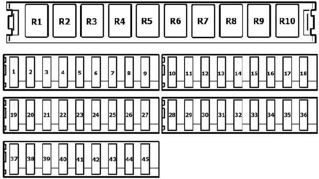
Relay
|
R1 |
Horn relay |
|
R2 |
Front wiper relay, mode 2 |
|
Wiper relay, stage 1/2 |
|
|
R3 |
Fuel pump relay |
|
Starter relay, terminal 15 (vehicles with code MI6/XM0) |
|
|
R4 |
Front wiper relay, mode 1 |
|
relay on/off wipers |
|
|
R5 |
Starter relay, terminal 50 |
|
R6 |
Relay, terminal 15R |
|
R7 |
Motor control relay, terminal 87 |
|
R8 |
Relay, terminal 15 |
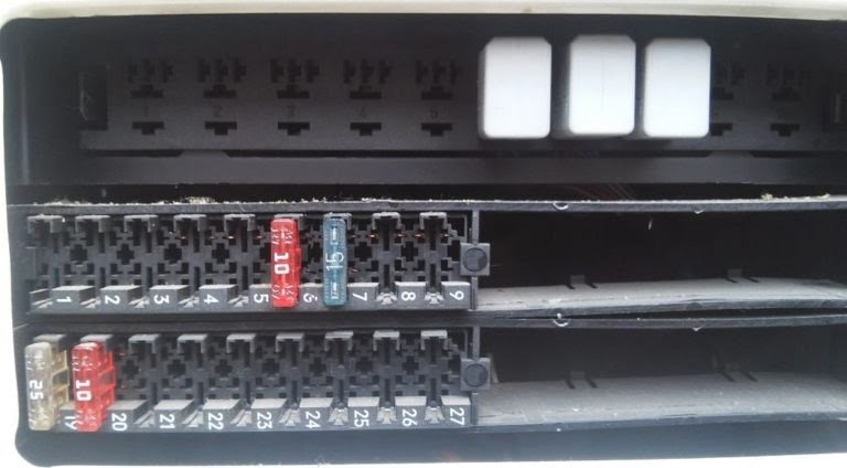
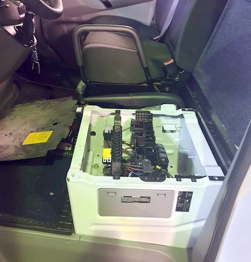
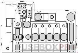
Fuse and relay boxes under the seat
On the left side, under the driver’s seat, there are several blocks with fuses and relays.
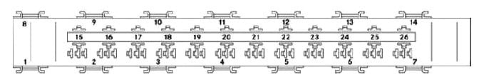
Fuse and relay box on the side of the seat
To access, remove the protective cover.
Type 1
Photo example
Diagram
Appointment
|
№ |
Amp |
Fuse Function |
|
1 |
5A |
Mirror adjustment, heated rear window relay |
|
2 |
30A |
Rear wiper |
|
3 |
5A |
Heater timer, Reversing camera, Neutral switch (with start assist, 4WD and keep engine running function), Electrical retrofit – DIN socket (roof), FleetBoard system, anti-theft system with vehicle tracking, emergency hammer lighting at the rear of the car, emergency exit lighting |
|
4 |
7.5A |
Tachograph, automatic speed control (ADR), power take-off, trailer coupling (AAG) |
|
5 |
10A Transmission Shift System (EGS) control unit, terminal 87 |
|
|
5A Start function, ECO engine shutdown, hood switch |
||
|
6 |
5A All wheel drive |
|
|
10A AWD, ride height control (ENR), auxiliary oil pump |
||
|
7 |
7.5/10/15A |
Automatic transmission control lever module (EWM) |
|
8 |
10A |
3-way tipping/tail lift, terminal 15, PARKTRONIC |
|
9 |
15A SSU/roof fan |
|
|
7.5A Air conditioning compressor clutch, switchable warning buzzer for reversing warning light |
||
|
10 |
25A |
Body equipment, terminal 30 |
|
11 |
15A |
Body equipment, terminal 15 |
|
12 |
10A |
Body equipment, terminal D+ |
|
13 |
10A Additional turn signal module (before 03/07) |
|
|
30A Rear air conditioner |
||
|
20A Fuel Pump FSCM (Fuel Level Control Module) |
||
|
15A Fuel pump relay without FSCM (vehicles with code MI6/XM0) |
||
|
14 |
20A |
Trailer socket |
|
15 |
25A |
Trailer coupler (AAG) |
|
16 |
7.5A |
Tire pressure monitoring system (RDK), Parktronic |
|
17 |
25A |
Control unit for parameterizable special module (PSM) |
|
18 |
25A |
Control unit for parameterizable special module (PSM) |
|
19 |
5/10A Ceiling control box (DBE) |
|
|
25A Sliding/tilting sunroof, overhead control box (DBE) |
||
|
10A “ERA-GLONASS” system |
||
|
20 |
7.5A |
Contour lights, number plate light, identification light |
|
21 |
30A Heated rear window without EDW (anti-theft alarm system) |
|
|
15A Heated rear window with EDW (anti-theft alarm system) |
||
|
22 |
15A Heated rear window |
|
|
20A Vehicle power socket |
||
|
23 |
10A Body Electrical, Third Party |
|
|
15A Socket in rear compartment, left |
||
|
24 |
15A |
Driver’s seat socket |
|
25 |
15A |
Socket in the rear of the passenger compartment on the right |
|
26 |
25A |
Auxiliary water heater |
|
27 |
25A Additional heater |
|
|
20A Additional air heater |
||
|
28 |
30A Rear air conditioning (until 03/07) |
|
|
7.5A CNG, terminal 87 |
||
|
25A Starter relay SRB (fuse and relay box; vehicles without back-up battery) |
||
|
25A Starter with support from the on-board network due to an additional battery |
||
|
29 |
10/30A Four wheel drive |
|
|
7.5A Terminal 87 (7) gas fuel system, cars with natural gas engine NGT |
||
|
30 |
30A Air suspension (compressor), brake booster (for North America) |
|
|
10A All wheel drive (compressor) |
||
|
15A Additional heat exchanger fan |
||
|
31 |
15/30A Sliding door left, rear fan |
|
|
15A Sliding door closing reinforcement, left |
||
|
32 |
10A Keyless Entry |
|
|
5A SCR system – exhaust gas aftertreatment control relay |
||
|
33 |
30A Sliding door right, suspension unit (ENR) |
|
|
15A Sliding door closing reinforcement, right |
||
|
34 |
30A Left sliding door (until 03/07) |
|
|
20A SCR system – heating system 1, AdBlue® reducing agent, vehicles with diesel exhaust aftertreatment system |
||
|
35 |
30A Brake booster |
|
|
5A SCR system – heating system 2, AdBlue® reducing agent, vehicles with diesel exhaust aftertreatment system |
||
|
36 |
15A |
SCR system – control and heating system 3, AdBlue® reducing agent, vehicles with diesel exhaust aftertreatment system |
|
37 |
5A |
COLLISION PREVENTION ASSIST / FCW (Forward Collision Warning) |
|
Lane Change Warning / BSM (Blind Spot Monitor) |
||
|
38 |
10A |
Multifunction Camera (MK) with High Beam Assist with Lane Departure Warning |
|
39 |
7.5A Body electrical equipment (delivery operation), reinforced air conditioning system in the rear of the vehicle |
|
|
15A Ceiling fan, siren |
||
|
40 |
15A |
Charging current from buffer battery (vehicles with buffer battery) |
|
41 |
7.5A |
SAM (signal acquisition and excitation module) buffer battery reference voltage |
|
42 |
30A |
Rear air conditioning system |
|
43 |
10A |
Electric step/sliding door, right |
|
44 |
10A |
Electric step/sliding door, left |
|
45 |
5A |
Electric step, control module and warning buzzer |
|
Relay |
|
|
R1 |
relay cl. D+ Body |
|
R2 |
relay cl. 15 body |
|
R3 |
Lighting relay |
|
Tail lift relay |
|
|
R4 |
Headlight washer relay |
|
R5 |
Flashing light relay |
|
R6 |
Horn relay EDW (EDW – anti-theft alarm system) |
|
R7 |
Not used |
|
R8 |
SGU relay |
|
R9 |
Circulation pump relay |
|
R10 |
Not used |
Type 2
Diagram
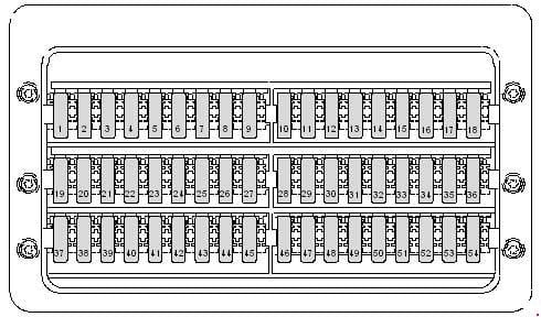
Decoding
|
№ |
Amp |
Fuse Function |
|
1 |
5A |
Window regulator control panel in the driver’s door Relay 2 for heated rear window |
|
2 |
30A |
Rear window wiper motor in swing door |
|
3 |
5A |
Timer Gearbox neutral position switch Display panel Rear view camera |
|
4 |
7.5A |
Switch for adjusting the operating speed PTO monitor sensor Trailer detection control unit Tachograph control unit |
|
5 |
5/10A |
Selector Control unit mech. Electronically controlled gearbox Bonnet limit switch (from November 2011) |
|
6 |
5/10A |
Heating resistor for crankcase ventilation system Control unit for battery regulation (from May 2011 to May 2013) |
|
7 |
10A |
Fuel filter heating element |
|
8 |
5/10A |
Tipping device button Parking aid control unit (from May 2013) Special superstructure relay, cl. 15 (up to November 2011) 6-pin connector -T6ah- 7-pin connector -T7f- (tail lift connector) |
|
9 |
15A |
Roof fan switch for supply ventilation of the cargo compartment (until November 2011) Siren relay (until November 2011) Not used (from November 2011) |
|
10 |
25A |
For the manufacturer of superstructures and special equipment |
|
11 |
15A |
Relay for special superstructures, cl. fifteen |
|
12 |
10A |
Relay for special superstructures, cl. 61 |
|
13 |
– |
Reserve |
|
14 |
20A |
Connector, 9-pin -T9b- (preparation for post-factory installation of trailer hitch) Hitch socket |
|
15 |
25A |
Trailer recognition control unit |
|
16 |
7.5A |
Parking aid control unit Tire pressure monitor control unit |
|
17 |
25A |
Control unit for programmable special functions |
|
18 |
25A |
Control unit for programmable special functions |
|
19 |
5/25A |
Roof electrical control unit |
|
20 |
7.5/10A |
Relay for pumping coolant after off. motor relay input illumination and footwell |
|
21 |
30A |
Rear window defogger relay |
|
22 |
15A |
Rear window heating relay 2 |
|
23 |
10/15A |
Load box lighting switch 12 V socket 2 -U18- |
|
24 |
15A |
Socket 12V 4 |
|
25 |
15A |
Socket 12V 3 |
|
26 |
25A |
Additional heater control unit |
|
27 |
20/25A |
Additional heater control unit |
|
28 |
30/40A |
Gearbox hydraulic pump relay, Starter relay 1 |
|
29 |
15A |
Control unit mech. Electronically controlled gearbox |
|
30 |
5A |
Battery regulation system control unit |
|
31 |
15/30A |
Control unit for left sliding door (from May 2012) Control unit for rear supply fan Rear supply fan |
|
32 |
5A |
Control unit for battery control |
|
33 |
7.5/15/30A |
Not used Right sliding door control unit (from May 2012) Transfer case interlock relay (from January 2012) Air compressor (from January 2012) |
|
34 |
7.5/15A |
Control unit for reducing agent heating system Gearbox sensor for differential lock |
|
35 |
3/15A |
Control unit for reducing agent heating system Compressor protection control unit (from January 2012) |
|
36 |
5A |
Not used (until January 2012) Compressor switch (from January 2012) |
|
37 |
– |
Reserve |
|
38 |
– |
Reserve |
|
39 |
7.5/15A |
Roof fan switch for supply ventilation of the cargo compartment (from November 2011) Siren relay (from November 2011) |
|
40 |
– |
Reserve |
|
41 |
– |
Reserve |
|
42 |
30A |
Evaporator fan control unit -J349- |
|
43 |
– |
Reserve |
|
44 |
– |
Reserve |
|
45 |
– |
Reserve |
|
46 |
– |
Reserve |
|
47 |
– |
Reserve |
|
48 |
– |
Reserve |
|
49 |
– |
Reserve |
|
50 |
– |
Reserve |
|
51 |
– |
Reserve |
|
52 |
– |
Reserve |
|
53 |
– |
Reserve |
|
54 |
– |
Reserve |
|
55 |
– |
Reserve |
|
56 |
– |
Reserve |
Relay under the seat
Additional relays can be installed under the seat itself.
Diagram
Assignment
|
R1 |
Starter relay, right-hand drive vehicles |
|
R2 |
Unload relay, terminal 15 |
|
R3 |
Relay, terminal 15, starter |
|
R4 |
Secondary Air Injection Relay / Secondary Air Pump |
|
SCR system relay, vehicles with exhaust after-treatment system |
|
|
R5 |
Fuel pump relay |
|
R6 |
Fan relay, front, fan stage 1 |
|
R7 |
Unload relay, terminal 15 R |
|
R8 |
Starter relay, auxiliary battery |
|
Starter relay, left-hand drive vehicles |
|
|
R9 |
Relay 1, heated rear window |
|
R10 |
Heated rear window relay 2 with EDW |
|
Snow plow relay, low beam left |
|
|
R11 |
Relay 1, left electric footrest |
|
Snow plow relay, right low beam |
|
|
R12 |
Relay 2, left electric footrest |
|
Snow plow relay, high beam left |
|
|
R13 |
Unload relay, terminal 15 (2) |
|
Snow plow relay, right high beam |
|
|
R14 |
Relay 1, heated windshield |
|
R15 |
Relay, bodybuilder, terminal 15 |
|
R16 |
Relay, bodybuilder, terminal 61 (D+) |
|
R17 |
Tail lift equipment relay |
|
Comfort lighting relay |
|
|
R18 |
Headlight cleaner relay |
|
R19 |
Beacon relay with siren |
|
R20 |
EDW (Emergency Warning System) Relay, Horn |
|
R21 |
Loop/Identifier Relay (North America) |
|
License Plate Lamp Relay (Public Service) |
|
|
Fan relay, additional air heating, fan stage 1 |
|
|
R22 |
Fan relay, additional air heating, fan stage 2 |
|
R23 |
Beacon relay with siren |
|
Relay, terminal 61 (D+), anti-theft device with vehicle tracking |
|
|
R24 |
Relay 1, right electric footrest |
|
R25 |
Relay 2, right electric footrest |
|
R26 |
Reverse signal relay off. |
|
Anti-theft device relay with vehicle tracking |
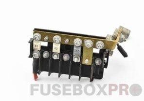
Power fuse box
When installing an additional battery under the seat, it can also be equipped with an additional high power fuse box.
Diagram
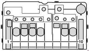
Designation
|
№ |
Amp |
FUse Function |
|
1 |
– |
Spare |
|
2 |
80A |
Signal Acquisition and Excitation Module (SAM) / Fuse and Relay Module (SRB) |
|
3 |
– |
Spare |
|
4 |
150A |
Buffer battery input |
|
5 |
150A |
SAM (signal acquisition and excitation module) / SRB (fuse and relay box), terminal 30 fuse box |
|
6 |
||
|
7 |
||
|
8 |
100A |
Brake – retarder, combined with battery disconnect relay |
|
9 |
150A |
Additional battery |
|
10 |
250A |
Snow plow drive hydraulic pump, Tail lift, Dump truck |
Diagram
Functions
|
№ |
Amp |
Fuse Function |
|
12 |
– |
Spare |
|
13 |
150A Electrical auxiliary heater (PTC) |
|
|
80A Rear air conditioning system, reinforced |
||
|
14 |
60A Air conditioning electric fan – cab without bulkhead or with heavy duty rear air conditioning (vehicles with a wheelbase of 3665 mm) |
|
|
40A Air conditioning electric fan – bulkhead cab or rear heavy duty air conditioning |
||
|
40A Air conditioning electric fan – cab, open vehicle modification |
||
|
70A Electric fan |
||
|
15 |
– |
Spare |
|
16 |
100A Retarder, not in combination with battery disconnect relay |
|
|
150A Battery Disconnect Relay |
||
|
17 |
– |
Spare |
|
18 |
300A |
Generator |
Battery fuse box
The fuse box is located near the battery in the footwell on the left side of the vehicle.
Diagram
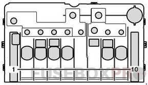
Appointment
|
№ |
Amp |
Fuse Function |
|
1 |
80A Engine preheat relay |
|
|
40A Secondary air pump (vehicles with petrol engine) |
||
|
2 |
80A Engine cooling fan – air conditioning |
|
|
25A Relay, terminal 15, starter (vehicles with code MI6/XM0; vehicles with back-up battery) |
||
|
25A Starter relay, no support (vehicles with backup battery) |
||
|
70A Engine cooling fan (vehicles without backup battery) |
||
|
40A Air conditioning fan – cab (vehicles without backup battery) |
||
|
40A Air Conditioning Fan – Cab with Bulkhead or Powered Rear Air Conditioning (Vehicles Without Buffer Battery) |
||
|
60A Air Conditioning Fan – Cab with Bulkhead or Powered Rear Air Conditioning (3665 mm wheelbase vehicles; vehicles without buffer battery) |
||
|
3 |
80A |
Signal acquisition and excitation module/fuse and relay box (vehicles without backup battery) |
|
4 |
150A |
Auxiliary battery in engine compartment, retarder (vehicles without backup battery) |
|
5 |
150A |
Terminal 30, fuse blocks, signal recording and excitation module/fuse and relay box (vehicles without backup battery) |
|
6 |
Seat frame reference point (bridge) |
|
|
7 |
150A Auxiliary heater (PTC) (vehicles without backup battery) |
|
|
80A Rear air conditioning system, reinforced (vehicles without backup battery) |
That’s all. And if you know how to make the material better – write in the comments.