Fuse box diagram Toyota Aygo 1G and relay with assignment and location

The 1st generation Toyota Aygo is produced in 2005, 2006, 2007, 2008, 2009, 2010, 2011, 2012, 2013 and 2014. During this time, the model has been updated 2 times. In our material you can find information on the location of electronic control units, a description of fuses and relays Toyota Aigo 1 with box diagrams and photo examples of their execution. Highlight the cigarette lighter fuse.
The arrangement of the blocks and the purpose of the elements in them may differ from that shown and depend on the year of manufacture, the level of equipment and the region of delivery of your car.
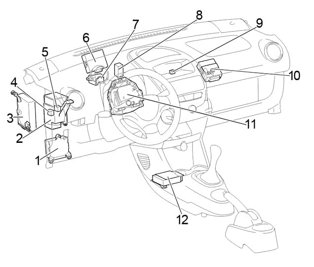
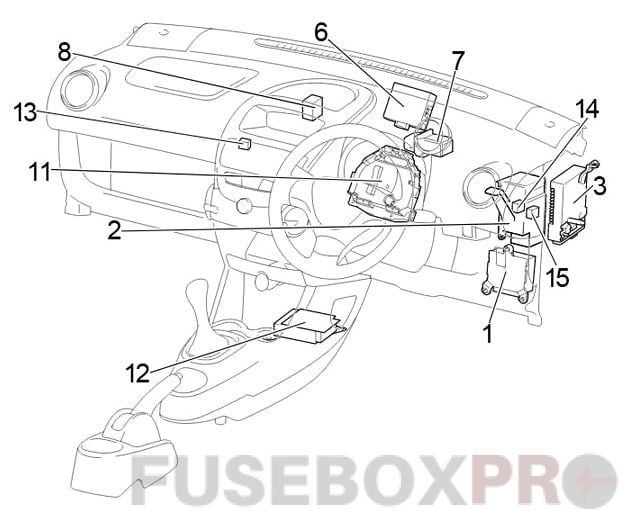
Passenger compartment
Location
Layout
Assignment
- Power Steering ECU
- Center Connector
- Multi-mode Manual Transmission ECU
- Power Window Relay
- LHD:
Before Feb. 2012: Tail Lamp Relay
From Feb. 2012: Rear Fog Lamp Relay - Door Control ECU with Receiver
- Relay Box No.1
- A/C Amplifier
- LHD: Fog Lamp Relay
- LHD: Running Light Relay
- Fuse Box
- Airbag Sensor Assembly Center
- RHD: Relay Box No.2
- RHD:
Before Feb. 2012: Ignition Relay (IG)
From Feb. 2012: Power Window Relay - RHD:
Before Feb. 2012: Power Window Relay
From Feb. 2012: Rear Fog Lamp Relay
Fuse box
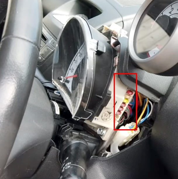
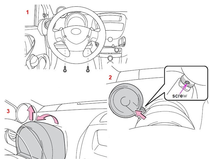
In the passenger compartment, the main fuse box is located on both sides of the speedometer, behind the protective box and consists of two parts.
In order to remove the protective cover, it is necessary to unscrew 3 screws. To do this, you will need to turn the steering wheel in different directions.
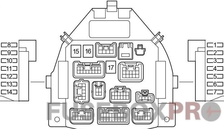
Diagram
Designation
| 1 | 10A STOP – Stop lights, high stop light, anti-lock braking system, multimode manual transmission |
| 2 | 25A D / L – Power door lock system, wireless remote control system |
| 3 | 20A DEF – Heated rear window |
| 4 | 7,5A TAIL – Daytime running light system, rear lights, license plate lighting, side lights, headlight level control system, instrument panel illumination |
| 5 | 7,5A OBD – On-board diagnostic system |
| 6 | 7,5A ECU-B – Multi-mode manual transmission, daytime running light system, vehicle stabilization system, sensors and instruments, rear fog lamp |
| 7 | – |
| 8 | 7,5A ECU-IG – Anti-lock braking system, vehicle stabilization system, electric power steering, electric cooling fan. |
| 9 | 10A BACK UP – Reversing lights, power door lock system, wireless remote control system, power windows, heated rear window, tachometer, air conditioning, heating system |
| 10 | 20A WIP – Windscreen wiper and washer, rear window wiper and washer |
| 11 | 15A ACC – Cigarette Lighter, Socket, Audio System |
| 12 | 7,5A IG1 – Windshield wiper and washer, rear window wiper and washer, anti-lock braking system, electric power steering system, electric cooling fan, reversing lights, power door locking system, wireless remote control system, power windows, rear window defogger , tachometer, air conditioning, heating system |
| 13 | 15A IG2 – Multiport fuel injection system / sequential multiport fuel injection system, SRS airbag system, gauges and instruments, daytime running light system, multi-mode manual transmission |
| 14 | 7,5A A / C – Air conditioning, electric heater |
| 15 | 40A AM1 – Fuses “ACC”, “WIP”, “ECU-IG”, “BACK UP” |
| 16 | 30A PWR – Power windows |
| 17 | 40A HTR – Heating system, air conditioning system, “A / C” fuse |
The fuse number 11 at 15A is responsible for the operation of the cigarette lighter.
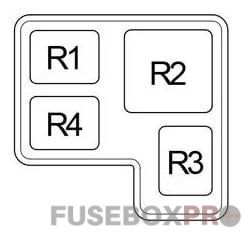
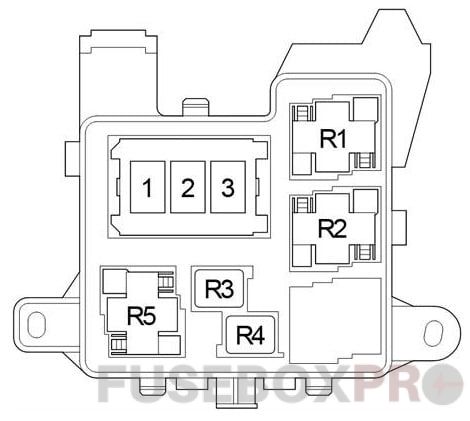
Relay box №. 1
Diagram
Protected components
| R1 | Accessory (ACC) |
| R2 | Heater (HTR) |
| R3 | Rear window defogger (DEF) |
| R4 | LHD: Ignition (IG) |
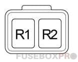
Relay box №. 2
Diagram
Functions
- R1 Ignition (IG)
- R2 Fog light (FOG)
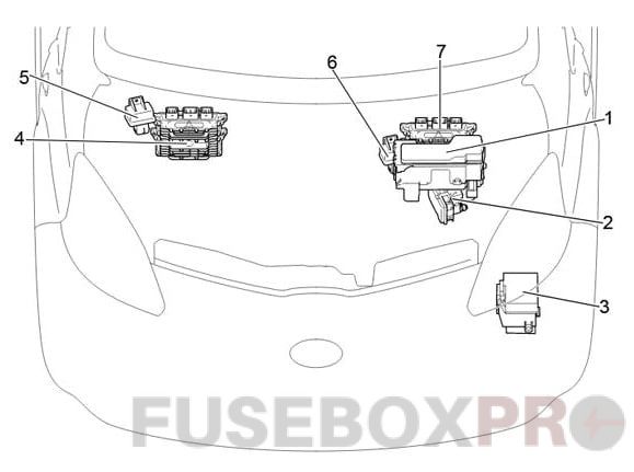
Engine compartment
Location
Layout
Appointment
- Fuse and Relay Box
- Skid Control ECU with Actuator
- Relay Box
- LHD: Engine ECU
- LHD: Glow Plug Relay
- RHD: Glow Plug Relay
- RHD: Engine ECU
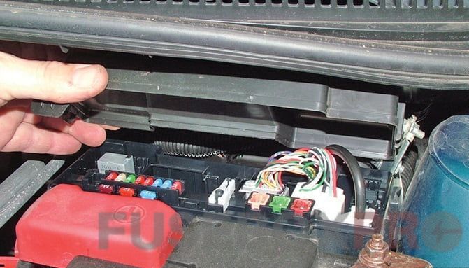
Fuse and relay box
Under the hood, the fuse and relay box is located next to the battery and is covered by a protective cover.
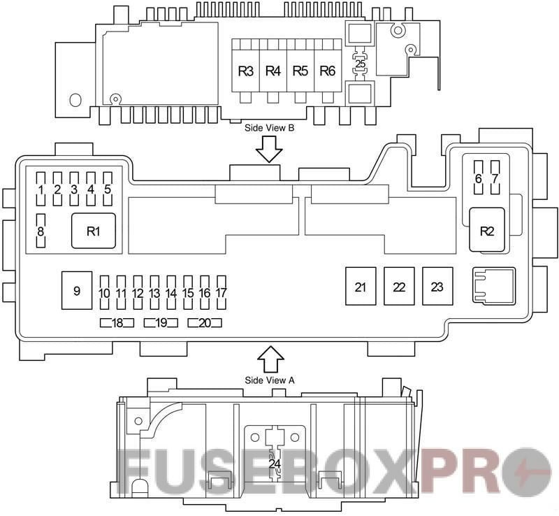
Diagram
Decoding
| 1 | 15A EFI NO.4 – 2WZ-TV: Multiport fuel injection system / sequential multiport fuel injection system |
| 2 | 10A H-LP RH (HI) – Before February 2012: Right-hand headlights. |
| 5A DRL – From February 2012: Daytime Running Lights. | |
| 3 | 10A H-LP LH (HI) – Before February 2012: Left headlight, sensors and instruments. |
| 20A FR FOG – From February 2012: Front fog lamps. | |
| 4 | 10A H-LP RH (LO) – Before February 2012: Right-hand headlights |
| 10A H-LP LH – From February 2012: Left headlight. | |
| 5 | 10A H-LP LH (LO) – Before February 2012: Left headlight, sensors and instruments. |
| 10A H-LP RH – From February 2012: Right-hand headlights. | |
| 6 | 7.5A STA – 1KR-FE: multi-mode manual transmission, multiport fuel injection system / sequential multiport fuel injection system. |
| 7,5A FAN NO.2 – 2WZ-TV: Electric cooling fan | |
| 7 | 7.5A EFI NO.2 – Multiport fuel injection system / sequential multiport fuel injection system, multimode manual transmission |
| 8 | 10A EFI NO.3 – 2WZ-TV: Multiport fuel injection system / sequential multiport fuel injection system, electric cooling fan. |
| 5A MET – Sensors and meters | |
| 9 | 50A AMT – 1KR-FE: Multi-mode manual transmission. |
| 50A RADIATOR FAN – 2WZ-TV: Electric cooling fan | |
| 10 | 10A H-LP LH – Without DRL: Headlight Left |
| Until February 2012: 20A DIMMER – with DRL: fuses “H-LP LH (HI)”, “H-LP RH (HI)”, “H-LP LH (LO)”, “H-LP RH (LO ) “, Daytime running lights system | |
| From Feb 2012: 30A SUB-LP – with DRL: “DRL”, “FOG FR” fuses | |
| 11 | 30A VSC NO.2 – Anti-lock braking system and vehicle stability control system |
| 25A ABS NO.2 – Without VSC: Anti-lock Braking System | |
| 12 | 30A AM2 – Starting system, fuses “IG1”, “IG2”, “STA” |
| 13 | 10A HAZARD – Direction indicators, emergency flashers, sensors and meters |
| 14 | 10A H-LP RH – Up to February 2012: Right-hand headlights. |
| 20A H-LP MAIN – From February 2012: fuses “H-LP LH”, “H-LP RH”. | |
| 15 | 15A DOME – Gauges and counters, interior lighting, audio system, tachometer. |
| 16 | 15A EFI – 1KR-FE: Electric cooling fan, multiport fuel injection system / sequential multiport fuel injection system |
| 25A EFI – 2WZ-TV: Electric cooling fan, multiport fuel injection system / sequential multiport fuel injection system. | |
| 17 | 10A HORN – Signal |
| 18 | 7.5A Spare fuse |
| 19 | 10A Spare fuse |
| 20 | 15A Spare fuse |
| 21 | 40A RADIATOR – Tropic: Electric cooling fan |
| 30A RADIATOR – Normal: electric cooling fan | |
| 22 | 50A VSC NO.1 – Anti-lock braking system and vehicle stability control system |
| 40A ABS NO.1 – Without VSC: Antilock Braking System | |
| 23 | 50A EMPS – Electric Power Steering |
| 24 | 120A ALTERNATOR – 1KR-FE: Charging system, “EPS”, “ABS (without vehicle stabilization system)”, “VSC (with vehicle stabilization system)”, “RADIATOR”, “AM1”, “HTR”, “PWR”, “Fuses D / L”, “DEF”, “TAIL”, “STOP”, “OBD”, “ECU-B” |
| 25 | EBD resistor |
| Relay | |
| R1 | Air Conditioning Compressor Clutch (A / C MAG) |
| R2 | Starter (ST) |
| R3 | Engine control unit (EFI MAIN) |
| R4 | 1KR-FE: Fuel pump (C / OPN) |
| R5 | Signal / Horn |
| R6 | Cooling system fan (FAN # 1) |
Relay box
Diagram
Assignment
- 1 –
- 2 80A PTC2 – Heater
- 3 80A PTC1 – Heater
- R1 PTC heater relay (PTC1) / Multi-mode manual transmission (MMT)
- R2 PTC heater relay (PTC2)
- R3 –
- R4 Before February 2012: Headlight (H-LP) / From February 2012: Daytime running lights (DRL).
- R5 Dimer (DIM)