Cadillac Fleetwood (1994) fuse box and relay Diagrams

The Cadillac Fleetwood of 1994 was a flagship luxury sedan renowned for its spaciousness, comfort, and powerful performance. Its electrical system, including the fuse box and relay components, was pivotal in ensuring smooth operation and reliability.
The fuse box in the Cadillac Fleetwood ’94 housed multiple fuses that protected various electrical circuits throughout the vehicle. These circuits powered critical components such as the engine control module, lighting systems, climate control, and entertainment features. Fuses were designed to prevent electrical overload by breaking the circuit if necessary, thereby safeguarding components from damage.
Relays in the Cadillac Fleetwood ‘94 functioned as electrically operated switches responsible for managing high-current circuits. They facilitated the precise activation and deactivation of functions such as the starter motor, fuel pump, air conditioning compressor, and power windows or seats. This efficient power distribution ensured reliable performance of the vehicle’s electrical systems.
Regular inspection and maintenance of the fuse box and relays were essential to uphold the Cadillac Fleetwood’s operational efficiency. This involved checking fuses for signs of wear or damage, ensuring relay connections were secure, and promptly addressing any electrical issues that arose. Proper care of these components contributed to maintaining the vehicle’s electrical integrity, enhancing safety and driving satisfaction in the Cadillac Fleetwood 1994.
MUST READ: DYI – How to Check Car Fuses?
(1994) Cadillac Fleetwood fuse box and relay with Diagram
WARNING
- Never replace a fuse with one that has a higher amperage rating.
- A fuse with a too-high amperage could damage the electrical part and cause a fire.
- On no account should fuses be repaired (e.g. patched up with tin foil or wire) as this may cause serious damage elsewhere in the electrical circuit or cause a fire.
- If a fuse blows repeatedly, do not keep replacing it. Instead, have the cause for the repeated short circuit or overload tracked and fixed.
- Terminal and harness assignments for individual connectors will vary depending on vehicle equipment level, model, and market.
Cadillac Fleetwood 1994 fuse assignment
Year of production: 1994
Instrument panel fuse block
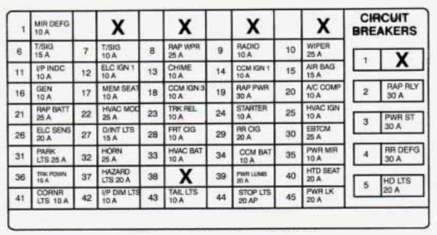
| Fuse number | Fuse name | Ampere rating | Usage |
| 1 | MIR DEFG | 10A | SIDEVIEW MIRROR DEFOGGERS |
| 2 | — | — | — |
| 3 | — | — | — |
| 4 | — | — | — |
| 5 | — | — | — |
| 6 | T/SIG | 15A | PARK/NEUTRALAND BACKUP LAMP SWITCH, TURN FLASHER |
| 7 | EBTCM/TPS | 10A | ELECTRONIC BRAKE AND TRACTION CNTRL. MOD. (EBTCM), THROlTLE POSITION SENSOR (TIPS) INTERFACE MODULE |
| 8 | RAP WPR | 25A | RETAINED ACCESSORY PWR. (RAP) WIPER RELAY |
| 9 | RADIO | 10A | RADIO RECEIVER |
| 10 | WIPER | 25A | WINDSHIELD WIPER/WASHER |
| 11 | I/P INDC | 10A | INFLATABLE RESTRAINT DIAGNOSTIC ENERGY RESERVE (WITH SENSOR) MODULE, INSTRUMENT PANEL CLUSTER INDICATORS |
| 12 | ELC IGN 1 | 10A | AUTOMATIC LEVEL CNTRL. SENSOR |
| 13 | CHIME | 10A | WARNING ALARM CRUISE CNTRL. RELEASE SWITCH, REAR WINDOW DEFOG. RELAY, INSULE REAR VIM MIRROR (DDB), CATALYTIC CONVERTER TEMP ALARM (JAPAN ONLY) |
| 14 | CCM IGN1 | 10A | CENTRAL CNTRL. MOD. (CCM) |
| 15 | AIR BAG | 15A | INFLATABLE RESTRAINT DIAGNOSTIC ENERGY RESERVE (WITH SENSOR) MOD. |
| 16 | GEN | 10A | ENGINE ELECTRICAL GENERATOR, SECONDARY ELECTRICAL ENGINE COOLING FAN RELAY |
| 17 | MEM SEAT | 10A | DRIVER’S SEAT MEMORY MOD., DRIVER SEAT ADJUSTER CNTRL. MOD., HEATED PASSENGER SEAT CNTRL MOD |
| 18 | CCM IGN 3 | 10A | REMOTE CARL. DOOR LOCK RECEIVER AND THE DETERRENT MOD |
| 19 | RAP PWR | 30A | RETAINED ACCESSORY PWR. (RAP) PWR RELAY |
| 20 | A/C COMP | 10A | A/C COMPRESSOR RELAY, PRIMARY ELECTRICAL ENGINE, COOLING FAN RELAY |
| 21 | RAP BATT | 25 | RETAINED ACCESSORY PWR. (RAP) WIPER RELAY |
| 22 | HVAC MOD. | 25A | A/C ELECTRILL CNTRL. MOD. |
| 23 | TRK REL | 10A | REAR COMPARTMENT LID RELEASE SW |
| 24 | STARTER | 10A | THEFT DELREN? RELAY INFLAT RESTRAINT DIAGNOSTIC ENERG RESERVE (WITH SENSOR) MOD |
| 25 | HVAC IGN | 10A | INSTRUMENT PANEL GAGE CLUSTER, HVAC.FOWER MOD |
| 26 | ELC SENS | 20A | AUTOMATIC LwEL ANTRL. SENSOR, REAR COMPARTMENT COURTESY LAMP |
| 27 | D/INT LTS | 15A | DELAYED INTERIOR LIGHTS (DIL) RELAY |
| 28 | FRT CIG | 10A | FRONT CIGAR LIGHTERS |
| 29 | RR CIG | 20A | REAR CIGAR LIGHTERS |
| 30 | EBTCM | 25A | ELECTR6NIC BRAKE &TRACTION CNTRL. MOD. (EBTCM) |
| 31 | PARK LT | 20A | FORWARD LAMP WIRING RELAY |
| 32 | HORN | 25A | HORN |
| 33 | HVAC BAT | 10A | WARNING ALARM, INSTRUMENT CLUSTER, HEADLAMP SWITCH, RADIO RECEIVER ALARM, HEATER AND NC CNTRL. ENGINE OIL LEVEL INDICATOR CNTRL~ MOD. |
| 34 | CCM BAT | 10A | CENTRAL CNTRL. MOD. (CCM) |
| 35 | PWR MIR | 10A | DOOR LOCKS, OUTSIDE REMOTE CNTRL. REARVIEW MIRRORS SWITCHES, PWR. SEAT BACK LUMBAR CNTRLS. |
| 36 | TRK PDWN | 15A | TRUNK LID PULL-DOWN UNIT |
| 37 | HAZARD LTS | 20A | HAZARD LAMP FLASHER |
| 39 | PWR LUM | 20A | PWR. SEAT BACK PNEUMATIC RADIO POWER ANTENNA RELAY CNTRL. MOD, RADIO POWER ANTENNA RELAY |
| 40 | HTD SEAT | 20A | DRIVERS HEATED SEAT CNTRL. MOD, PASSENGER HEATED SEAT CNTRL. MOD |
| 41 | CORNR LTS | 10A | INSTRUMENT CLUSTER, RADIO CNTRL., TURN SIGNAL SWlTCH |
| 42 | I/P DIM LTS | 10A | HEADLIGHT SWITCH, INTERIOR LIGHTS, DIMMING CNTRL |
| 43 | TAIL LTS | 10A | REAR TAIL LIGHTS, REAR SIDE MARKER LIGHTS, LICENSE LAMP |
| 44 | STOP LTS | 20A | STOP LAMP SWITCH |
| 45 | PWR LK | 20A | DOOR LOCK RELAY |
| C/B 1 | — | — | — |
| C/B 2 | RAP RELAY | 30A | RETAINED ACCESSORY PWR. (RAP) RELAY |
| C/B 3 | PWR ST | 30A | DRIVERS PWR. SEAT SW., PASSENGER PWR. SEAT SW. , MEMORY SEAT MOD |
| C/B 4 | RR DEFG | 30A | REAR DEFOGGER RELAY |
| C/B 5 | HD LTS | 30A | HEADLIGHT RELAY, DAYTIME RUNNING UGHTS (DRL) |
Underhood (U/H) Electrical Center
The U/H electrical center is located on the passenger side wheel housing in the engine compartment.
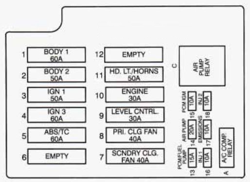
| Fuse number | Fuse name | Ampere rating [A] | Usage |
| 1 | BODY 1 – I/P FUSE BLOCK | 60A | #3 PWR. SEAT CIRCUIT, BREAKER (30 AMP), #36 TRUNK PULL-DOWN (15 AMP), #37 HAZARD LTS. (20 AMP), #39 PWR. LUMBAR (20 AMP), #40 HEATED SEAT (20 AMP), #44 STOP LTS. (20 AMP), #45 PWR. LOCK (20 AMP) |
| 2 | BODY 2 – I/P FUSE BLOCK | 50A | #21 RAP BAT (25 AMP), #22 HVAC MDL. (25 AMP), #26 ELC. SENS. (20 AMP), #27 D/INT LTS. (15 AMP), #28 FRT CIG. (10 AMP), #29 RR. CIG. (20 AMP), #30 EBTCM (25 AMP), #33 HVAC BAT (10 AMP), #34 CCM BAT (10 AMP), #35 PWR. MIR. (10 AMP), #2 CIRCUIT BREAKER – RAP RLY (30 AMP) |
| 3 | IGN 1 | 50A | I/P CONCEALED FUSE, RKE/UTD SA, I/P FUSE BLOCK, #6 T/SIS-ICA, #7 EBTCMDPS (10 AMP), #8 RAP WPR. (25 AMP), #9 RADIO (10 AMP), #10 WIPER (25 AMP), #11 I/P IiDC (10 AMP), #12 ELC. IGN. 1 (10 AMP), #13 CHIME (10 AMP), #14 CCM IGN 1 (10 AMP), #15 AIR BAG (15 AMP), #24 STARTER, U/H ELC. CNTR., #15 PCM/IGN (10AMP), #16 INJ 1 (10AMP), #17 EMISSIONS (10 AMP), #18 INJ 2 (10 AMP) |
| 4 | IGN 3 | 40A | I/P FUSE BLOCK, #16 GEN. (10 AMP), #17 MEM. SEAT (10 AMP), #18 CCM IGN 3 (10 AMP), #19 RAP PWR. (30 AMP), #20 A/C COMF! (10 AMP), #25 HVAC IGN (10 AMP) |
| 5 | ABS/TC | 60A | BRAKE PRESSURE MODULATOR VALVE (BPMV) |
| 6 | — | — | — |
| 7 | SCNDRY CLG FAN | 40A | SECONDARY COOLING FAN CNTRL. RELAY |
| 8 | PRIMRY CLG FAN | 40A | PRIMARY COOLING FAN CNTRL. REIAY |
| 9 | LEVEL CNTRL | 30A | AUTOMATIC LEVEL CNTRL AIR COMR |
| 10 | ENGINE | 30A | #13 PCM/FUEL PUMP (15 AMP), #14 AIR PUMP (20 AMP) |
| 11 | I/P FUSE BLOCK CIRCUIT BREAKER | #5 HDLTS (20 AMP), #31 PARK LTS. (20 AMP), #32 HORN (25 AMP) | |
| 12 | — | — | — |
| 13 | PCM FUEL PUMP | 15A | FUEL PUMP RELAY, FUEL PUMP AND ENGINE OIL PRESSURE INDICATOR SWITCH, POWER TRAIN CONTRL MDL (PCM) |
| 14 | AIR PUMP | 20A | SECONDARY AIR IN (AIR) PUMP RELAY |
| 15 | PCM IGN | 10A | IGN COIL, ELECTRONIC TRANS., (PCM) POWER TRAIN CNTRL. MDL |
| 16 | INJ 1 | 10A | FUEL INJ 1,4,6,7 |
| 17 | EMISSIONS | 10A | (A.I.R.) PUMP‘RELAY, MASS AIR FLOW (MAF) SENSOR, HEATED OXYGEN SENSOR’S, EVAPORATIVE EMISSIONS CANNISTER PURGE SOLONOID VALVE |
| 18 | INJ 2 | 10A | FUEL INJ 2,3,5,8 |
Conclusion
For owners and enthusiasts of classic Cadillac Fleetwood 1994, understanding the fuse box and relay systems is essential for vehicle maintenance. Regular inspection and maintenance of these components helped ensure the vehicle’s longevity and reliability, preserving its status as a symbol of Cadillac’s craftsmanship and innovation in the automotive industry during that era.