Cadillac Fleetwood (1993) fuse box and relay Diagrams
The Cadillac Fleetwood of 1993 was a flagship luxury sedan renowned for its spaciousness, comfort, and powerful performance. Its electrical system, including the fuse box and relay components, was pivotal in ensuring smooth operation and reliability.
The fuse box in the Cadillac Fleetwood ’93 housed multiple fuses that protected various electrical circuits throughout the vehicle. These circuits powered critical components such as the engine control module, lighting systems, climate control, and entertainment features. Fuses were designed to prevent electrical overload by breaking the circuit if necessary, thereby safeguarding components from damage.
Relays in the Cadillac Fleetwood ‘93 functioned as electrically operated switches responsible for managing high-current circuits. They facilitated the precise activation and deactivation of functions such as the starter motor, fuel pump, air conditioning compressor, and power windows or seats. This efficient power distribution ensured reliable performance of the vehicle’s electrical systems.
Regular inspection and maintenance of the fuse box and relays were essential to uphold the Cadillac Fleetwood’s operational efficiency. This involved checking fuses for signs of wear or damage, ensuring relay connections were secure, and promptly addressing any electrical issues that arose. Proper care of these components contributed to maintaining the vehicle’s electrical integrity, enhancing safety and driving satisfaction in the Cadillac Fleetwood 1993.
MUST READ: DYI – How to Check Car Fuses?
(1993) Cadillac Fleetwood fuse box and relay with Diagram
WARNING
- Never replace a fuse with one that has a higher amperage rating.
- A fuse with a too-high amperage could damage the electrical part and cause a fire.
- On no account should fuses be repaired (e.g. patched up with tin foil or wire) as this may cause serious damage elsewhere in the electrical circuit or cause a fire.
- If a fuse blows repeatedly, do not keep replacing it. Instead, have the cause for the repeated short circuit or overload tracked and fixed.
- Terminal and harness assignments for individual connectors will vary depending on vehicle equipment level, model, and market.
Cadillac Fleetwood 1993 fuse assignment
Year of production: 1993
Instrument panel fuse block
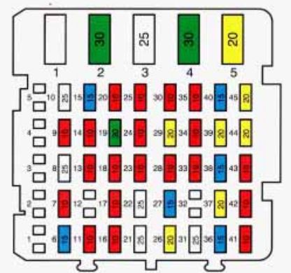
| Fuse number | Fuse name | Ampere rating | Usage |
| 1 | — | — | — |
| 2 | — | — | — |
| 3 | — | — | — |
| 4 | — | — | — |
| 5 | — | — | — |
| 6 | T/SIG | 15A | PARK/NEUTRALAND BACKUP LAMP SWITCH, ELECTRIC TURN FLASHER |
| 7 | ABS | 10A | ELECTRONIC BRAKE CNTRL. MOD. (EBCM) |
| 8 | RAP WPR | 25A | RETAINED ACCESSORY PWR. (RAP) |
| 9 | RADIO | 10A | RADIO RECEIVER |
| 10 | WIPER | 25A | WINDSHIELD WIPER/WASHER |
| 11 | I/P INDC /TELLTAIL | 10A | DIAGNOSTIC ENERGY RESERVE, LOW COOLANT MOD. (DERM), LOW COOLANT MOD, INSTRUMENT PANEL CLUSTER INDICATORS |
| 12 | — | — | — |
| 13 | CHIME | 10A | CHIME MOD., SPEED SENSOR BUFFER MOD., TORQUE CONVERTER CLUTCH (TCC) DISIBLE RELAY, AUTO DAY/NIGHT MIRROR, REAR DEFOGGER RELAY |
| 14 | CCM | 10A | CENTRAL CNTRL. MOD. (CCM), THROTTLE POSITION (TP) SENSOR MOD., ELECTRONIC LEVEL CNTRL (ELC) |
| 15 | AIR BAG | 10A | DUAL POLE ARMING SENSOR |
| 16 | CRUISE | 10A | GENERATOR, CRUISE CNTRL |
| 17 | HTD ST | 10A | DRIVER’S MEMORY SEAT, DRIVER HEATED SEAT, PASSENGER HEATED SEAT |
| 18 | CCM IGN | 10A | CENTRAL CNTRL. MOD. (CCM), INSTRUMENT CLUSTER, REMOTE KEYLESS ENTRY/UNVERAL THEFT DETERRENT RECEIVER |
| 19 | RAP PWR | 10A | RETAINED ACCESSORY PWR. (RAP) |
| 20 | HVAC | 10A | HVAC SOLENOID MOD., INSTRUMENT CLUSTER, HVAC CNTRL. HEAD |
| 21 | RAP BATT | 25A | RETAINED ACCESSORY PWR. (RAP) WIPER RELAY |
| 22 | HVAC | 25A | HVAC PWR. MOD. |
| 23 | TRK REL | 10A | TRUNK LID RELEASE SW |
| 24 | STARTER | 10A | STARTER ENABLE REALY. DIAGNOSTIC ENERGY RESERV MOD. (DERM) |
| 25 | MIR DEFG | 10A | SIDE VIEW MIRROR DEFOGGERS |
| 26 | PWR ANT | 20A | TRUNK LAMP, HVAC PWR. M&D. PWR. ANTENNA |
| 27 | D/INT LPS | 15A | DELAYED INTERIOR LIGHTS (DIL) |
| 28 | FRT CIG | 10A | FRONT CIGAR LIGHTE |
| 29 | RR CIG | 20A | REAR CIGAR LIGHTERS |
| 30 | HVAC | 10A | HVAC CNTRL. ASSEMBLY |
| 31 | ABS | 25A | ELECTRONIC BRAKE AND TRACTION CNTRL. MOD |
| 32 | — | — | — |
| 33 | CLUSTER | 10A | CHIME MOD., INSTRUMENT CLUSTER, LOW ENGINE OIL MOD., HEADLIGHT SW., RADIO RECEIVER |
| 34 | CCM | 10A | CENTRAL CNTRL. MOD. (CCM) |
| 35 | PWR LK | 10A | PWR. DOOR LOCKS, PWR. MIRRORS, PWR. LUMBAR SEATS |
| 36 | TRK PDWN | 15A | TRUNK LID PULL-DOWN UNIT |
| 37 | STOP LPS | 20A | BRAKE TRANSMISSION SHIFT INTERLOCK IBTSIVSTOP LIGHT BRAKE SW. |
| 38 | PWR RECL | 15A | DRIVER-SCT RECLIfiE SW., PASSENGER SEAT RECLINE SW. |
| 39 | PWR LUMB | 20A | PWR. LUMBARSEAT MOTOR CNTRL MOD. |
| 40 | HTD ST | 15A | DRIVERR AND PASSENGER HEATEL, SEAT CNTRL. MOD. RELAY |
| 41 | CORNR LP | 10A | INSTRUMENT CLUSTER, RADIO CNTRL. HEAD, CORNERING LIGHTS |
| 42 | INT DIM | 10A | HEADLIGHT SWITCH, INTERIOR LIGHTS, DIMMING |
| 43 | RR T/LPS | 10A | REATTAIL LIGHTS, REAR SIDE MARKER LIGHTS, LICENSE LAMP |
| 44 | HZRD LP | 20A | HAZARD WARNING FLASHER |
| 45 | PWR LK | 20A | PWR. DOOR LOCK RELAY |
| C/B 1 | — | — | — |
| C/B 2 | RAP PWR | 30A | RETAlNED ACCESSh PWR. (RAP) RELAY |
| C/B 3 | PWR ST | 25A | DRIVERS PWR. SEAT SW., PASSENGER PWR. SEAT SW., MEMORY SEAT MOD. |
| C/B 4 | RR DEFG | 30A | REAR DEFOGGER REALY |
| C/B 5 | HDLP | 30A | HEADLIGHT RELAY, DAMIME RUNNING LIGHTS (DRL) |
Underhood (U/H) Electrical Center
The U/H electrical center is located on the passenger side wheel housing in the engine compartment.
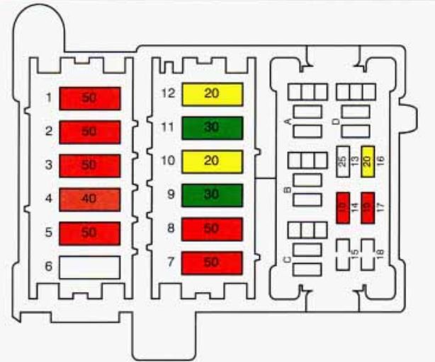
| Fuse number | Fuse name | Ampere rating [A] | Usage |
| 1 | BODY 1 | 50A | #45 PWR. DR. LOCK RELAY, #36 TRUNK PULL-DOWN, #37 STOP/HAZARD, #38 RECLINE SW., #39 PWR. LUMBAR, #40 HEATED SEAT, #3 PWR. SEAT CIRCUIT BREAKER, $4 REAR DEFOG RELAY CIRCUIT BREAKER, #44 MIRROR DEFOG |
| 2 | BODY 2 | 50A | #26 I/P-PWR. ANTENNA #27 l/P-DELAYED INTERIOR LIGHTS (DRL)- #28 WFRONT CIGAR, #29 I/P-REAR CIGAR, #30 I/P-HVAC CNTRL. HEAD, #21 IIP-RAP ACCESSORY RELAY, #22 I/P-HVAC PWR. MOD., #23 WTRUNK RELEASE, #9 I/P-RADIO, #10 I/P-RAP ACCESSORY, #31 I/P-TRACTION CNTRL. LIGHTS (DIL), #33 GP-TELTALE, #34 I/P-CCM 2, #35 I/P-PWR. DR. LOCK SW., #18 U/H-AIR PUMP, #2 CIRCUIT BREAKER I/P-RAP PWR. RELAY |
| 3 | IGN 1 | 50A | #6 I/P-RETAINED ACCESSORY PWR. (RAP), #6 I/P-TURN FLASHER, #24 I/P-CRANK, #15 I/P-AIR BAG, #11 I/P-TELTALE, #14 I/P-CENTRAL CNTRL. MOD. (CCM), #13 I/P-CHIME, #7 I/P-TRACTION CNTRL., #13 U/H-INJECTORS, #14 U/H-ENGINE CNTRL. MOD. (ECM), IN-LINE CONCEALED I/P-REMOTE KEYLESS ENTRY RECEIVER, IGNITION COI |
| 4 | IGNS3 | 40A | #I6 I/P-CRUISE, #I7 I/P-HEATED SEATS, #18 I/P-CCM IGNITION, #19 WRAP PWR. RELAY, #20 I/P-HVAC CNTRL. HEAD , #17 U/H-COOLING FAN RELAY |
| 5 | ABS | 50A | ANTILOCK BRAKE SYSTEM/TRACTION CNTRL. (ABSKC) HYDRAULIC MODULATOR |
| 6 | — | — | — |
| 7 | PRIMRY CLG FAN | 50A | PRIMARY COOLING FAN RELAY |
| 8 | SCNDRY CLG FAN | 50A | SECONDARY COOLING FAN RELAY |
| 9 | LEVEL CNTRL | 30A | #15 U/H-ELECTRONIC LEVEL CNTRL. (ELC) |
| 10 | FUEL PUMP | 20A | #16 U/H-FUEL PUMP |
| 11 | HEADLlGHTS/HORNS | 30A | #1 F/L-HORN RELAY , #2 F/L-HEADLIGHTS RELAY, #5 CIRCUIT BREAKER I/P-HEADLIGHTS |
| 12 | PARK LIGHTS | 20A | #4 F/L-PARK LIGHTS, #5 F/L-FORWARD LIGHTS, #41 I/P-CORNERING LIGHTS, #42 I/PI-DIMMER, #43 I/P-REAR TAIL LIGHTS |
| 13 | INJECTORS | 10A | FUEL INJECTORS, ENGINE CNTRL. MOD. (ECM) |
| 14 | EGR/PCM (IGN) | 10A | EXHAUST GAS RECIRCULATION (EGR) VALVE, AIR PUMP RELAY, PURGE CANISTER |
| 15 | LEVEL CNTR | 20A | ELECTRONIC LEVEL CNTRL. (ELC) HEIGHT SENSOR, ELC COMPRESSOR/RELAY ASSEMBLY |
| 16 | FUEL PUMP | 10A | ENGINE CNTRL. MOD. (ECM), FUEL PUMP RELAY, FUEL PUMP/OIL PRESSURE SW. |
| 17 | COOLING FANS | 10A | SECONDARY COOLING FAN RELAY, COOLING FANS CNTRL. RELAY |
| 18 | AIR PUMP | 20A | AIR PUMP RELAY |
| A | — | — | — |
| B | COOLING FANS CNTRL. RELAY | — | COOLING FAN CNTAL. RELAY |
| C | A/C DISABLE RELAY | — | AIR COND. DISABLE RELAY |
| D | FUEL PUMP RELAY | — | FUEL PUMP RELAY |
Forward Light (FIL) Electrical Center
The foward lighting electrical center is located on the driver’s side in front of the windshield washer fluid container.
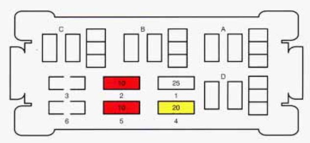
| Fuse number | Fuse name | Ampere rating [A] | Usage |
| 1 | HORN | 25A | HORN RELAY (COIL), HORNS |
| 2 | HDLP | 10A | HEADLIGHT RELAY (COIL), DAYTIME RUNNING LIGHTS (DRL) RELAY |
| 3 | — | — | — |
| 4 | PARK LP | 20A | PARK LIGHT RELAY |
| 5 | FRT PARK LP | 10A | FRONT MARKER LIGHTS, FRONT SIDE MARKER LIGHTS |
| 6 | — | — | — |
| A | — | — | — |
| B | DRL RLY | — | DAYTIME RUNNING LIGHTS (DRL) RELAY |
| C | HORN RELAY | — | HORN RELAY |
| D | PARK LP RELAY | — | PARK LIGHTS RELAY |
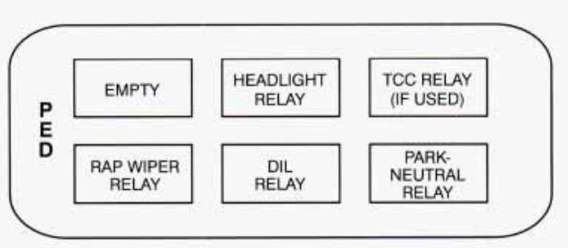
Instrument Panel Relay Center
This relay center is located left of the steering column compartment.
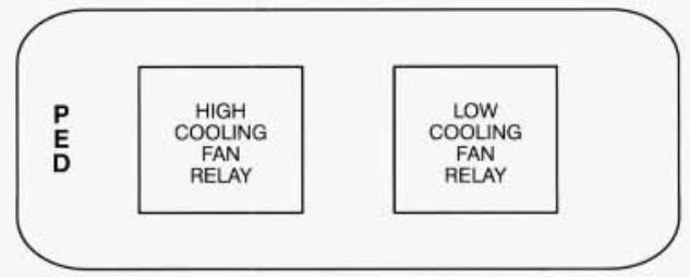
Cooling Fan Relay Center (If Equipped)
This relay center is located on the passenger side bulk head in the engine compartment.
Conclusion
For owners and enthusiasts of classic Cadillac Fleetwood 1993, understanding the fuse box and relay systems is essential for vehicle maintenance. Regular inspection and maintenance of these components helped ensure the vehicle’s longevity and reliability, preserving its status as a symbol of Cadillac’s craftsmanship and innovation in the automotive industry during that era.