BMW Z4 E85 & E86 fuse box and relay Diagrams (2002-2008)

The BMW Z4 E85 and E86 models were manufactured between 2002 and 2008, representing the second generation of the Z4 series. These roadsters are equipped with a range of advanced electrical components, including a sophisticated fuse box and relay system that helped to manage and control the various electronic systems within the car. In this article, we will explore the various electrical components of the BMW Z4 E85 and E86, including the location and function of the fuse box and relay.
The Fuse Box System
The BMW Z4 E85 and E86 feature a highly advanced fuse box system, which is designed to provide protection and control for the various electrical systems within the car. The fuse box is located in the glove compartment on the passenger side of the vehicle, and is easily accessible for quick maintenance and repair.
The BMW Z4 E85 and E86 fuse box contains a variety of different fuses, each of which is responsible for protecting a different electrical system within the car. The fuses are arranged in a specific pattern, with each row corresponding to a different system. For example, the first row of fuses controls the air conditioning and heating system, while the second row controls the car’s lighting system. A diagram of the fuse box and its fuses is typically printed on the back of the glove compartment, making it easy for drivers to quickly identify and replace any blown fuses.
The Relay System
In addition to the fuse box, the BMW Z4 E85 and E86 also feature a sophisticated relay system, which helps to manage the flow of electrical current throughout the car. The relays are located in various locations throughout the vehicle, and are responsible for controlling a range of different electrical systems, including the headlights, air conditioning, and power windows.
The BMW Z4 E85 and E86 relay system is highly complex, and can be difficult for inexperienced drivers to diagnose and repair. However, with the help of a reliable wiring diagram and some basic electrical knowledge, it is possible for drivers to troubleshoot and fix many common relay issues on their own. In addition, BMW service technicians are highly trained in the maintenance and repair of the Z4’s electrical systems, and can provide expert assistance for more complex issues.
(2002-2008) BMW Z4 E85 & E86 fuse box and relay with Diagram
WARNING
- Never replace a fuse with one that has a higher amperage rating.
- A fuse with a too-high amperage could damage the electrical part and cause a fire.
- On no account should fuses be repaired (e.g. patched up with tin foil or wire) as this may cause serious damage elsewhere in the electrical circuit or cause a fire.
- If a fuse blows repeatedly, do not keep replacing it. Instead, have the cause for the repeated short circuit or overload tracked and fixed.
BMW Z4 (E85 & E86) 2002-2008 fuse assignment
Passenger Compartment Fuse Box
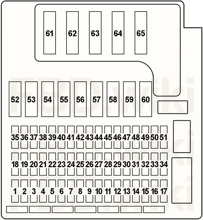
| No. | Amps | Assignment/Designation |
| 1 | ||
| 2 | 10A | – |
| 3 | 30A | – |
| 4 | 30A | – |
| 5 | 15A | Front Cigar Lighter |
| 6 | 10A | Reversing Light Switch (Manual Transmission), Reversing Light Relay ((→08.2004) – Automatic Transmission, SMG) |
| 7 | 5A | Steering Angle Sensor DSC, “Sport” Button, Dynamic Stability Control (DSC) |
| 8 | 5A | Driver’s Door Module, Park Distance Control (PDC), Cigar Lighter Relay |
| 9 | 7.5A | →08.2004: Oil Level Sensor, Transmission Control (Automatic Transmission), Sequential Manual Transmission (SMG) |
| 7.5A | 03.2005→: Data Link Connector (OBD II), Integrated Supply Module (IVM (N52)) | |
| 10 | 5A | 03.2005→: General Module Control Unit, Auxiliary Water Pump, Electronic Vehicle Immobilizer (EWS) |
| 11 | 25A | General Module Control Unit |
| 12 | 5A | General Module Control Unit, Electronic Vehicle Immobilizer (EWS), Centre Console Switch Centre, Instrument Cluster Control Unit |
| 13 | 5A | →12.2005: Safety and Information Module, Seat Occupancy Recognition |
| 5A | 01.2006→: Rain/Headlight Sensor, Volume Spring | |
| 14 | 5A | Secondary Air Pump Relay, Light Switch Cluster, Clutch Switch Module, Brake Light Switch |
| 15 | 30A | →12.2005: Passenger’s Seat Adjustment Switch (LHD), Driver’s Seat Memory (RHD) |
| 30A | 01.2006→: Passenger’s Seat Adjustment Switch | |
| 16 | 25A | Centre Console Switch Center |
| 17 | – | – |
| 18 | – | – |
| 19 | 20A | Fuel Pump Relay |
| 20 | 20A | →12.2005: Rear Window Defogger Relay |
| 30A | 01.2006→: Rear Window Defogger Relay | |
| 21 | 5A | Heated Spray Nozzles Thermal Switch (→02.2004), Passenger’s Side Outside Mirror, Steering Column Switch (Cruise Control (01.2006→)) |
| 22 | 5A | Heating/Air Conditioning System, Electronic Power Steering (EPS) |
| 23 | 5A | Light Switch Cluster, Instrument Cluster Control Unit |
| 24 | 5A | Instrument Cluster Control Unit, Data Link Connector (OBD II), Steering Angle Sensor DSC, Gear Indicator Lighting (USA), Auxiliary Water Pump (S54) |
| 25 | 5A | Electrochromic Interior Rear View Mirror, Digital Motor Electronics (DME) Control Unit, Terminal 15 Power-Saving Relay, Rear Window Defogger Relay |
| 26 | 30A | General Module Control Unit |
| 27 | 5A | Outside Mirror Fold-in |
| 28 | 5A | →12.2005: Steering Column Switch (Cruise Control), Rain/Headlight Sensor, Volume Spring |
| 5A | 01.2006→: Crash Safety Module, Airbag Indicator Light, Seat Occupancy Recognition | |
| 29 | 30A | →12.2005: Driver’s Seat Memory (LHD), Passenger’s Seat Adjustment Switch (RHD) |
| 30A | 01.2006→: Driver’s Seat Memory | |
| 30 | 7.5A | →12.2005: Horn for Antitheft Alarm System, Tilt Sensor, Interior Movement Detector, Electrochromic Interior Rear View Mirror |
| 5A | 01.2006→: Dynamic Stability Control (DSC) | |
| 31 | 20A | Roadster: Convertible Top Module |
| 32 | 7.5A | →12.2005: Sequential Manual Transmission (SMG) |
| 7.5A | 01.2006→: Digital Motor Electronics (DME) Control Unit | |
| 33 | 10A | Fuel Pump Relay, Secondary Air Pump Relay, E-Box Fan, Diagnostic Module for Fuel Tank Leakage (→08.2004) |
| 34 | – | – |
| 35 | – | – |
| 36 | 15A | Front Fog Lights Relay |
| 37 | 15A | Horn Relay |
| 38 | 30A | Wiper Relay No.1 & 2 |
| 39 | 7.5A | →12.2005: Heating/Air Conditioning System |
| 7.5A | 01.2006→: Heating/Air Conditioning System, Siren and Tilt Alarm Sensor, Interior Movement Detector, Electrochromic Interior Rear View Mirror | |
| 40 | 30A | Headlight Washer Pump Relay |
| 41 | 5A | Driver’s Window Motor, Passenger’s Window Motor |
| 42 | 30A | →12.2005: Dynamic Stability Control (DSC) |
| 40A | 01.2006→: Dynamic Stability Control (DSC) | |
| 43 | 30A | →12.2005: Dynamic Stability Control (DSC) |
| 20A | 01.2006→: Dynamic Stability Control (DSC) | |
| 44 | 5A | 01.2006→: Fuel Pump Control (EKPS) |
| 45 | 10A | →12.2005: Safety and Information Module |
| 10A | 09.2006→: Tyre Pressure Control (RDC) | |
| 46 | 30A | General Module Control Unit |
| 47 | 7.5A | Navigation System, Radio, Basic Interface Telephone, Telephone Transceiver, Eject Box (→12.2005), Voice Control System |
| 48 | 7.5A | CD Changer |
| 49 | 10A | Central Information Display (CID), Navigation System, Video Module, Basic Interface Telephone (Japan), Compensator (except Japan), Eject Box (except Japan), Telephone Transceiver (except Japan), Voice Control System (except Japan) |
| 50 | 30A | Radio, Amplifier |
| 51 | – | – |
| 52 | – | – |
| 53 | – | – |
| 54 | 40A | Ignition Switch |
| 55 | 40A | Roadster: Convertible Top Relay No.: 1 & 2 |
| 56 | 50A | Secondary Air Pump Relay |
| 57 | 40A | Blower Output Stage |
| 58 | 40A | Ignition Switch |
| 59 | 40A | Light Switch Cluster |
| 60 | 40A | Light Switch Cluster |
| 61 | 60A | Electric Fan |
| 62 | – | – |
| 63 | 80A | →12.2005: B+ Potential Distributor |
| 60A | 01.2006→: B+ Potential Distributor | |
| 60A | N52: B+ Potential Distributor, Integrated Supply Module (IVM), Fuel Injectors Relay, Digital Motor Electronics (DME) Control Unit, DME Relay, Variable Valve Gear Relay | |
| 64 | 100A | Electronic Power Steering (EPS) |
| 65 | – | – |
- N46B20 – 2.0i
- M54B22 – 2.2i
- M54B25 – 2.5i
- M54B30 – 3.0i
- N52B25 – 2.5i & 2.5si
- N52B30 – 3.0si
- S54B32 – M 3.2i
Relay Location
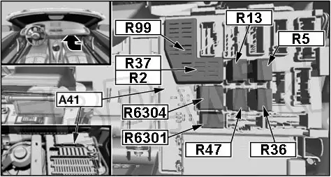
| No. | Relay |
| R2 | Horn |
| R5 | Headlight Washer Pump |
| R13 | Rear Window Defogger |
| R36 | Wiper Relay No.1 |
| R37 | Wiper Relay No.2 |
| R47 | Front Fog Light |
| R99 | Rear Window Defogger |
| 6301 | Fuel Pump |
| 6304 | Secondary Air Pump |
| R1 | Roadster: Convertible Top Relay No.1 |
| R2 | Roadster: Convertible Top Relay No.2 |
| R3 | Outside Mirror Fold-in Module |
| R4 | RHD: Convertible Top Relay No.2 |
| R5 | RHD: Cigar Lighter |
| R6 | Terminal 15 Relief |
Engine Compartment Fuses
| No. | Amps | Assignment/Designation |
| Main Fuse Box (Battery) | ||
| 100 | 250A | Power Distribution (Passenger Compartment Fuse Box) |
| 101 | 100A | N52: Integrated Supply Module (IVM) |
| 100A | N46: Fuse No.: “0001” (40A – Variable Valve Timing Gear Relay) | |
| 102 | 40A | Amplifier (TopHifi) |
| 2.0i (N46) | ||
| Location | ||
| 01 | 20A | Fuel Injectors |
| 02 | 20A | →08.2005: Intake VANOS Solenoid Valve, Exhaust VANOS Solenoid Valve, Camshaft Sensor 1 & 2, Characteristic Map Cooling Thermostat |
| 20A | 09.2005→: Hot-Film Air Mass Meter, Oil Level Sensor, Crankshaft Sensor, Fuel Tank Vent Valve, Digital Motor Electronics (DME) Control Unit | |
| 03 | 20A | →08.2005: Hot-Film Air Mass Meter, Oil Level Sensor, Crankshaft Sensor, Fuel Tank Vent Valve, Digital Motor Electronics (DME) Control Unit, Crankcase Breather Heating |
| 30A | 09.2005→: Oxygen Sensor before Catalytic Converter, Oxygen Sensor after Catalytic Converter, Oxygen Sensor before Catalytic Converter No.2 (RHD), Oxygen Sensor after Catalytic Converter No.2 (RHD) | |
| 04 | 10A | →08.2005: Fuse No.: “33” |
| 10A | 09.2005→: Fuse No.: “33”, Intake VANOS Solenoid Valve, Exhaust VANOS Solenoid Valve, Camshaft Sensor 1 & 2, Characteristic Map Cooling Thermostat | |
| 05 | 30A | →08.2005: Oxygen Sensor before Catalytic Converter, Oxygen Sensor after Catalytic Converter, Oxygen Sensor before Catalytic Converter No.2 (RHD), Oxygen Sensor after Catalytic Converter No.2 (RHD) |
| 30A | 09.2005→: Terminal 15 Power-Saving Relay | |
| 001 | 30A | Terminal 15 Power-Saving Relay |
| 0001 | 40A | Variable Valve Timing Gear Relay |
| 2.2i, 2.5i, 3.0i (M54) | ||
| Location | ||
| 01 | 30A | Ignition Coils |
| 02 | 30A | Intake VANOS Solenoid Valve, Exhaust VANOS Solenoid Valve, Individual Control Intake System Valve, Fuel Tank Vent Valve, Idle Actuator, Digital Motor Electronics (DME) Control Unit, Characteristic Map Cooling Thermostat (09.2003→) |
| 03 | 20A | Hot-Film Air Mass Meter, Crankshaft Sensor, Characteristic Map Cooling Thermostat (→08.2003), Camshaft Sensor No. 1 & 2, Reversing Light Relay, Fuse No.: “33” |
| 04 | 30A | Oxygen Sensor before Catalytic Converter No.1 & 2, Oxygen Sensor after Catalytic Converter No.1 & 2, Transmission Control (Automatic Transmission), Sequential Manual Transmission (SMG) |
| 05 | 30A | Fuel Injectors Relay |
| Relay (M54) | ||
| R1 | Fuel Injectors | |
| R2 | Digital Motor Electronics (DME) Control Unit | |
| R3 | Reversing Light | |
| R4 | Transmission Control | |
| 2.5i, 2.5si, 3.0i, 3.0si Roadster and 3.0si Coupe (N52) | ||
| Location | ||
| 01 | 20A | Characteristic Map Thermostat, Crankshaft Sensor, Intake Camshaft Sensor, Exhaust Camshaft Sensor, Intake VANOS Solenoid Valve, Exhaust VANOS Solenoid Valve, Oil Condition Sensor, DISA Actuator 1 & 2, Air Mass Flow Sensor |
| 02 | 10A | Digital Motor Electronics (DME) Control Unit |
| 03 | 30A | Variable Valve Timing Gear Relay, Digital Motor Electronics (DME) Control Unit |
| 04 | 30A | Crankshaft Breather Heating, Oxygen Sensor before Catalytic Converter No.1 & 2, Oxygen Sensor after Catalytic Converter No.1 & 2 |
| 05 | – | – |
| 06 | 30A | Ignition Coils, Interference Suppression Capacitor for Ignition Coils |
| 07 | 20A | Fuel Injectors |
| 08 | 30A | Electric Coolant Pump |
| 09 | 40A | Digital Motor Electronics (DME) Control Unit |
| Relay (N52) | ||
| R1 | Digital Motor Electronics (DME) Control Unit | |
| R2 | Variable Valve Timing Gear | |
| R3 | Fuel Injectors | |
| R4 | Reversing Light | |
| 010 | 5A | Crankshaft Breather Heating Relay (Location: Fuse / Relay) |
| 3.2L (S54) M Roadster & M Coupe | ||
| Location | ||
| 01 | 30A | Ignition Coils, Interference Suppression Capacitor for Ignition Coils |
| 02 | 30A | Digital Motor Electronics (DME) Control Unit, Oil Condition Sensor, Suction Jet Pump Valve, Idle Actuator, Fuel Tank Vent Valve, Crankcase Breather Valve |
| 03 | 20A | Digital Motor Electronics (DME) Control Unit, Hot-Film Air Mass Meter, Intake Camshaft Sensor, Exhaust Camshaft Sensor, Fuse No.: “33” |
| 04 | 30A | Oxygen Sensor before Catalytic Converter No.1 & 2, Oxygen Sensor after Catalytic Converter No.1 & 2 |
| 05 | 30A | Fuel Injectors Relay |
| Relay | ||
| R1 | Fuel Injectors | |
| R2 | Digital Motor Electronics (DME) Control Unit | |
| 1a | 30A | Location: SMG Hydraulic Pump Relay |
| Relay | ||
| R1 | – | |
| R2 | – | |
| R3 | Location: SMG Hydraulic Pump | |
| R4 | – | |
In conclusion, the BMW Z4 E85 and E86 models feature a highly advanced electrical system, including a sophisticated fuse box and relay system, which helps to manage and control the various electronic systems within the car. Understanding the location and function of these components is critical for maintaining and repairing the car’s electrical systems, and can help drivers to diagnose and fix many common issues on their own. By working with reliable wiring diagrams and seeking out expert assistance when needed, drivers can enjoy the full range of features and capabilities offered by the BMW Z4 E85 and E86.