Audi A2 fuse box and relay Diagrams (1999-2005)
The Audi A2 is a compact car produced by Audi from 1999 to 2005. It is the first Audi model with a space frame design, making it lighter and more fuel-efficient. The A2 is also known for its advanced technology and safety features, making it a popular choice among drivers who prioritize both efficiency and safety.
One of the key components of the Audi A2’s advanced technology is its electrical system, which includes a fuse box and relay that are responsible for regulating the electrical flow throughout the car. In this article, we will take an in-depth look at the Audi A2’s electrical system, including the location and function of the fuse box and relay. We will also discuss common issues that may arise with these components and how to diagnose and fix them.
Electrical System Overview
The Audi A2’s electrical system is comprised of several components, including the battery, alternator, starter motor, fuse box, and relay. These components work together to ensure the proper functioning of the car’s electrical system.
Fuse Box and Relay Location
The Audi A2’s fuse box and relay are located in the engine compartment, on the driver’s side. To access the fuse box and relay, simply lift the cover of the compartment. Inside, you will find several fuses and relays that control various electrical functions of the car.
Fuse Box and Relay Functions
The fuse box is responsible for protecting the car’s electrical system from overloading or short-circuiting. It contains several fuses that will blow out if an electrical overload occurs, preventing damage to the system. The relay, on the other hand, is responsible for switching on and off various electrical components of the car, such as the headlights and air conditioning system.
Common Issues and Fixes
While the Audi A2’s electrical system is known for its reliability, there are some common issues that may arise with the fuse box and relay. One of the most common issues is a blown fuse, which can be caused by a short circuit or electrical overload. If this occurs, simply replace the blown fuse with a new one of the same amperage.
Another issue that may arise is a faulty relay, which can cause various electrical components of the car to malfunction or stop working altogether. To diagnose a faulty relay, use a multimeter to test its functionality. If the relay is found to be faulty, simply replace it with a new one.
Overall, the Audi A2’s electrical system, including its fuse box and relay, is a crucial component of the car’s advanced technology and safety features. Regular maintenance and prompt diagnosis and repair of any issues that arise can help ensure the proper functioning of the car’s electrical system, and a safe and enjoyable driving experience.
(1999-2005) Audi A2 fuse box and relay with Diagram
Audi A2 1999-2005 Fuse box locations
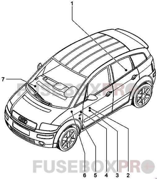
Fitting locations overview
1 – Main fuse 150 A2 – Relay carrier (9-point)3 – Fuse box
4 – Relay carrier (6+6-point)
5 – Relay carrier (3-point)
6 – Connector point, A pillar, left
7 – Connector point, A pillar, right
Main fuse
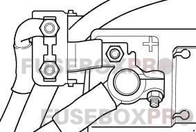
On battery
| № | Amps | Assignment/Designation |
| S88 | 150 A | Strip fuse |
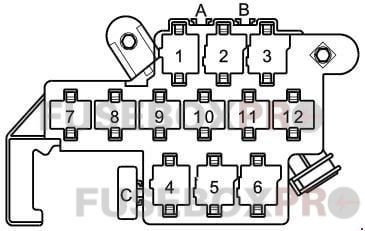
Relay carrier (9-point)
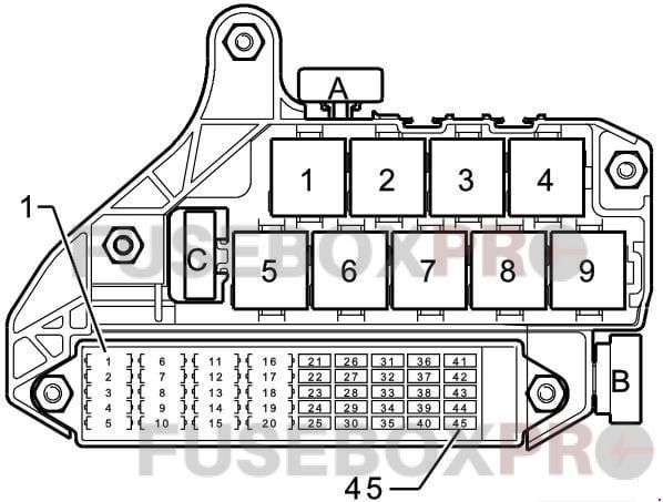
| № | Assignment/Designation | Amps |
| A | Multi-function steering wheel fuse (S326) | 1A |
| В | Additional heater fuse (S126) | 60A |
| C | Radiator fan control unit fuse (S142) | 40A |
| 1 | Control unit with display in dash panel insert | 10A |
| 2 | Voltage stabilizer | 20A |
| 3 | 4LV (injection system) control unit Ignition coil -1- with the output stage Ignition coil -2- with output stage Ignition coil -3- with output stage Ignition coil -4- with output stage |
20A |
| 4 | Radiator fanRadiator fan thermo-switch | 20A |
| 6 | Automatic intermittent wash/wipe relay Washer pump switch Intermittent wiper switch |
25A |
| 7 | Hazard warning light relay | 15A |
| 8 | Dual tone horn relay Horn/dual tone hom Sliding sunroof adjustment control unit |
25A |
| 10 | Trailer socket | 30A |
| 11 | 12 V socket | 20A |
| 12 | Cigarette lighter | 15A |
| 13 | Heated driver’s seat regulatorHeated front passenger’s seat regulator | 15A |
| 14 | Low heat output relay | 30A |
| 14 | Heater control unit | 20A |
| 15 | Air соnditioning system/Climatronic operating and display unit Heated rear window Heated rear window relay |
30A |
| 16 | Fresh air blower switch Fresh air blower control unit |
30A |
| 18 | Fuel pump (pre-supply pump) | 20A |
| 19 | Mobile telephone operating electronics control unit Telephone/telematics control unit Aerial amplifier, mobile telephone |
20A |
| 20 | Lambda probe heaterLambda probe 1 heater, downstream of the catalytic converter Activated charcoal filter system solenoid valve 1 (pulsed) NOx sensor control unit |
20A |
| 22 | Twin filament bulb for headlight, left | 10A |
| 23 | Bulb check warning unitHeadlight range control motor, right Twin filament bulb for headlight, right |
15A |
| 24 | Bulb check warning unitHeadlight range control motor, left Twin filament bulb for headlight, left |
15A |
| 25 | Bulb check warning unit Tail light bulb, left Sidelight bulb, left |
5A |
| 26 | Bulb check warning unit Tail light bulb, right Side light bulb, right |
5A |
| 27 | Bulb check warning unit Tail light bulb, left Side light bulb, left |
5A |
| 28 | Diagnostic connector | 10A |
| 29 | Diagnostic connector Reversing light switch | 15A |
| 30 | Brake light switch | 10A |
| 31 | Brake light switch. Heater element (crankcase breather) (MPI engine, diesel engine)Air mass meter low heat output relayHigh heat output relayCruise control system switch. Radiator fan control unit. Additional air heater control unitExhaust gas recirculation valve | 10A |
| 32 | Glove box light. Number plate light, left Number plate light, right |
10A |
| 33 | Heater element, left washer jet Heater element, right washer jet |
5A |
| 34 | Hazard warning light relay | 10A |
| 35 | Rear left fog light bulbFront and rear fog light switch | 15A |
| 36 | Ignition key withdrawal lock solenoid valve Electronic manual gearbox control unit Handbrake warning lamp control unit Ignition key withdrawal lock control unit |
10A |
| 37 | Navigation system with CD drive control unit Parking aid control unit |
10A |
| 38 | Automatic anti-dazzle interior mirror | 10A |
| 38 | Compressor regulating valve, air conditioning system Heated rear window relay Fresh air/air recirculating flap switch Operating electronics control unit, navigation Electronic manual gearbox control unit Parking aid control unit Power steering control unit Navigation system with CD drive control unit Telephone/telematics control unit Ignition key withdrawal lock control unit Additional heating button (ECON)AmplifierHazard warning light switch |
10A |
| 39 | Door control unit, front passenger’s side Door control unit, rear right |
10A |
| 40 | Traction соntrol system warning lamp Traction control system switch ABS with EDL control unit Steering angle sender |
10A |
| 41 | Door control unit, driver’s side Door control unit, rear left |
10A |
| 42 | Anti-theft alarm ultra-sonic sensorConvenience system central control unit | 10A |
| 43 | Electronic manual gearbox control unit | 10A |
| 44 | Ignition key withdrawal lock solenoid valve Electronic manual gearbox control unit Handbrake warning lam p control unit Ignition key withdrawal lock control unit |
10A |
| 45 | Ignition key withdrawal lock solenoid valve Electronic manual gearbox control unit Handbrake warning lamp control unit Ignition key withdrawal lock control unit |
15A |
| Relays | ||
| 1 | X Contact relief relay (J59) | |
| 4 | Consumer switch-off relay (J511) | |
| 5 | Dual tone horn relay (J4) | |
| 6 | Bulb check warning unit (K41) | |
| 7 | Bulb check warning unit (K41) | |
| 8 | Low heat output relay (J359) | |
| 9 | X contact relief relay (J59) | |
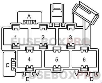
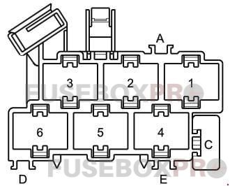
Relay carrier (6+6-point)
In the footwell, front left
| № | Assignment/Designation | |
| 1* | Starter inhibitor and reversing light relay (J226) | |
| 2 | Automatic intermittent wash/wipe relay (J31) | |
| 3 | Automatic intermittent wash/wipe relay (J31) | |
| 4* | Gearbox hydraulic pump relay (J510) | |
| 5* | Ignition key withdrawal lock control unit (J557) | |
| 5** | Fuel pump relay (J17) | |
| 6* | Ignition key withdrawal lock control unit (J557) | |
| № | Designation | Amps |
| A | Hydraulic pump relay fuse (S279) | 20A |
| C | ABS control unit fuse 1 (S123) | 60A |
* – Only applies to engine code ANY
** – Only applies to engine codes BAD, BBY
Relay carrier (3-point)
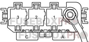
| № | Assignment/Designation | Amps |
| A* | Strip fuse for glow plugs (engine) (S39) | 40A |
| A** | Engine control unit fuse (S102) | 30A |
| A*** | Strip fuse for glow plugs (engine) (S39) | 60A |
| B* | Engine control unit fuse (S102) | 10A |
| B** | Air mass meter fuse (S74) | 5A |
| B*** | Engine control unit fuse (S102) | 10A |
| C | Fuse -1 – (30) (power steering) (S204) | 80A |
| Relays | ||
| 1* | Terminal 30 voltage supply relay (J317) | |
| 1** | Motronic current supply relay (J271) | |
| 1*** | Relay for glow plugs (J52) | |
| 2* | Automatic glow period control unit (J179) | |
| 2*** | Terminal 30 voltage supply relay (J317) | |
* – Only applies to engine code ATL
** – Only applies to engine code BAD
*** – Only applies to engine codes AMF, ANY, BHC
Connector point, A pillar, left
| № | Assignment/Designation | Amps |
| A | Electric w indow single fuse (front) (S37) | 30A |
| C | Seat adjustment fuse (lumbar support) (S45) | 10A |
Connector point, A pillar, right
| № | Assignment/Designation | Amps |
| C | Electric window single fuse 2 (rear) (S280) | 30A |
In conclusion, the Audi A2’s advanced technology and safety features, along with its fuel efficiency, make it a popular choice among drivers. The car’s electrical system, including its fuse box and relay, is a crucial component of its technology, and proper maintenance is necessary to ensure its reliability. By understanding the location and function of the fuse box and relay, as well as common issues and fixes, Audi A2 owners can better maintain their cars and enjoy a safe and enjoyable driving experience.