Audi A1/Audi S1 fuse box and relay Diagrams (2010-2018)

The Audi A1 is a subcompact luxury car that is produced by the German automaker Audi from 2010 to 2018. It is launched as a direct competitor to the Mini Cooper and is available in both three-door and five-door hatchback body styles. The S1 variant is introduced in 2014, which is the first high-performance version of the A1. The A1 and S1 models are known for their impressive build quality, high-end materials, and sporty handling.
This article will provide an in-depth guide to the electrical components of the Audi A1 and S1, with a focus on the fuse box and relay diagrams. Understanding the location and function of these components is essential for any owner or mechanic who wants to properly maintain or repair these vehicles.
Fuse Box
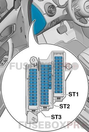
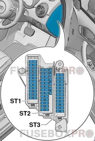
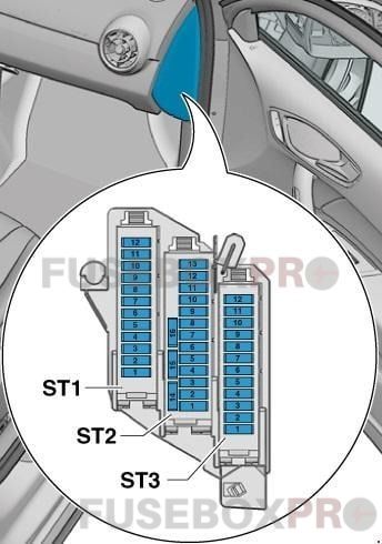
The fuse box in the Audi A1 and S1 is located on the left side of the dashboard, behind the storage compartment. The fuse box houses a variety of fuses that protect the electrical systems of the vehicle. Each fuse is designed to protect a specific component, and if a fuse blows, it will need to be replaced with a new one of the same amperage rating.
There are also spare fuses included in the fuse box, as well as a fuse removal tool for easy replacement. It is important to note that if multiple fuses blow at the same time, it may be an indication of a larger electrical issue that should be diagnosed by a professional mechanic. Regularly checking and replacing blown fuses can help prevent damage to the vehicle’s electrical systems.
Relay
The relays in the Audi A1 and S1 are also located in the fuse box on the left side of the dashboard. Relays are electrical switches that are activated by a control signal and allow a larger current to flow through to another component in the vehicle. There are several relays in the Audi A1 and S1, including those for the cooling fan, fuel pump, and power windows.
If a relay fails, it can cause problems with the associated component, such as a malfunctioning cooling fan or fuel pump. It is important to ensure that the relays are properly seated in the fuse box and that they are functioning correctly. If a relay needs to be replaced, it should be done with a genuine Audi part to ensure proper function and compatibility with the vehicle’s electrical system.
(2010-2018) Audi A1/Audi S1 fuse box and relay with Diagram
WARNING
- Never replace a fuse with one that has a higher amperage rating.
- A fuse with a too-high amperage could damage the electrical part and cause a fire.
- On no account should fuses be repaired (e.g. patched up with tin foil or wire) as this may cause serious damage elsewhere in the electrical circuit or cause a fire.
- If a fuse blows repeatedly, do not keep replacing it. Instead, have the cause for the repeated short circuit or overload tracked and fixed.
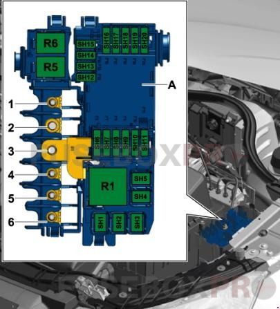
Audi A1/Audi S1 2010-2018 fuse box overview
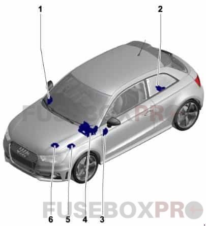
- Fuse holder D -SD-
- Fuse holder A -SA-
- Fuse holder C -SC-
- Relay/fuse holder F -SF-
- Fuse holder B -SB-, Fuse holder H -SH-
- Fuse holder B -SB-
Fuse holder A -SA-
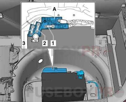
At battery-positive terminal (for models with battery in luggage compartment only)
| No. | Amps | Assignment/Designation |
| 1 | – | Vacant |
| 2 | 110A | Onboard supply Engine component supply |
| 3 | – | Vacant |
Fuse holder B -SB-
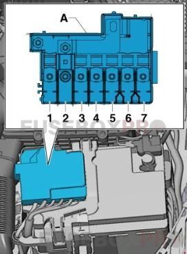
| No. | Amps | Assignment/Designation |
| 1 | 175A | Alternator -C- |
| 2 | 40A | Low heat output relay -J359- Heater element for auxiliary air heater -Z35- |
| 3 | 110 1)A | Onboard supply1) Engine component supply1) |
| 4 | 80A | Power steering control unit -J500- |
| 5 | 50 2)A 40 3)A |
Radiator fan thermal switch -F18- Radiator fan control unit -J293- |
| 6 | 50A | Automatic glow period control unit -J179- |
| 7 | 60A | High heat output relay -J360- Battery monitor control unit -J3671) Auxiliary heater element -Z35- |
1) for models with battery in engine compartment only
2) no longer fitted, phased out (model year 2011)
3) phased-in modification (model year 2011)
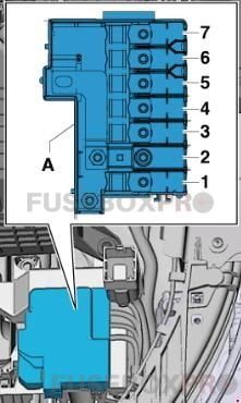
Fuses in electronics box in fuse holder B -SB-/ Fuse holder H -SH-

- In the electronics box, in left engine compartment.
- For S1 version models only, from January 2014
- For models from November 2014 only.
| No. | Amps | Assignment/Designation |
| 1 | 110 4)A
5 5)A |
Onboard supply4) Engine component supply4) Radiator fan control unit -J293-5) Radiator fan -V7-5) |
| 2 | 250A | Alternator -C- Voltage regulator -C1- |
| 3 | – | Battery + |
| 4 | 80A | Power steering control unit -J500- |
| 5 | 50 6)A | Automatic glow period control unit -J179-6) Glow plug 1 -Q10- Glow plug 2 -Q11- Glow plug 3 -Q12- Glow plug 4 -Q13- |
| 6 | 50 7)A
– 8) |
Radiator fan control unit -J293-7) Radiator fan -V7-7) – |
| 125A | Onboard supply8) Engine component supply8) |
- for models with battery in engine compartment only, up to October 2014
- for models from November 2014 only
- for models with diesel engines only, from November 2014
- for models up to October 2014
- for models with battery in engine compartment only, from November 2014
- Fuse 5 on fuse holder B -SB5- bridged, (see note)
Fuses in electronics box in fuse holder H -SH-
| No. | Amps | Assignment/Designation |
| 1 | 40A | Heater element for auxiliary air heater -Z35-, stage 1 |
| 2 | 30A | Radiator fan control unit -J293- Radiator fan -V7- |
| 3 | – | Vacant |
| 4 | 40A | Heater element for auxiliary air heater -Z35-, stage 2 |
| 5 | 40A | Heater element for auxiliary air heater -Z35-, stage 3 |
| 6 | 30A | Mechatronic unit for dual clutch gearbox -J743- |
| 7 | 7.5A | Engine control unit -J623- |
| 8 | 20A | Wiper motor switch-over relay 1 -J368- Wiper motor switch-over relay 2 -J369- |
| 9 | 5A | Battery monitor control unit -J367- |
| 10 | 10A | Suppression filter -C24- |
| 11 | – | Vacant |
| 12 | 10 12)A 15 13)10)11)A |
Lambda probe heater -Z19- Lambda probe 1 heater after catalytic converter -Z29- |
| 13 | 5A | Brake light switch -F- Clutch position sender -G476- |
| 14 | 5 13)A 10 10)11)12)A |
Thermal switch for air conditioning system shut-off -F163- Fuel metering valve -N290- Oil pressure regulation valve -N428- Cylinder head coolant valve -N489- Coolant circulation pump -V50- Circulation pump -V55- Charge air cooling pump -V188- Auxiliary heating pump -V488- |
| 15 | 5A | Onboard supply control unit -J519-, T52c/34 Engine control unit -J623-, T91/67;T94/… Voltage stabiliser -J532-, T12aa/4 |
| 16 | 30A | Starter motor -B- |
| 17 | 15 12)13)A 30 10)11)A |
Engine control unit -J623- |
| 18 | 5 10)11)A 10 12)13)A |
Oil level and oil temperature sender -G266- Fuel pump relay -J17- Radiator fan control unit -J293- Low heat output relay -J359- High heat output relay -J360- Charge pressure control solenoid valve -N75- Recirculation valve for turbocharger -N249- Intake manifold flap valve -N316- Oil pressure regulation valve -N428- Cooling oil valve -N471- |
| 19 | 7.5 10)A 10 11)13)A 20 12)A |
Engine component current supply relay -J757- Fuel pressure regulating valve -N276- Fuel metering valve -N290- Injector 2 for cylinder 1 -N532- Injector 2 for cylinder 2 -N533- Injector 2 for cylinder 3 -N534- Injector 2 for cylinder 4 -N535- Actuator 1 for camshaft adjustment -F366- Actuator 2 for camshaft adjustment -F367- Actuator 3 for camshaft adjustment -F368- Actuator 4 for camshaft adjustment -F369- Actuator 5 for camshaft adjustment -F370- Actuator 6 for camshaft adjustment -F371- Actuator 7 for camshaft adjustment -F372- Actuator 8 for camshaft adjustment -F373- Vacuum pump for brakes -V192- |
| 20 | 5 10)11)A 10 13)A 20 12)A |
Automatic glow period control unit -J179- Exhaust flap control unit -J883- Crankcase breather heater element -N79- Activated charcoal filter solenoid valve 1 -N80- Camshaft control valve 1 -N205- Exhaust camshaft control valve 1 -N318- Continued coolant circulation pump -V51- Sender 1 for secondary air pressure -G609- Sender 2 for secondary air pressure -G610- |
10) for models with 1.4 l diesel engine only
11) for models with 1.6 l diesel engine only
12) for models with 1.0 l/1.4 l petrol engine only
13) for models with 1.8 l/2.0 l petrol engine only
Fuse holder C -SC-
| No. | Amps | Assignment/Designation |
| Black | ||
| 1 | 30A | Digital sound package control unit -J525- Voltage stabiliser -J532- Radio -R- |
| 2 | 40A | Heater control unit -J65- X-contact relief relay -J59- Fresh air blower control unit -J126- Fresh air blower -V2- |
| 3 | 20A | Cigarette lighter -U1- 12 V socket -U5- |
| 4 | 15A | Trailer detector control unit -J345- |
| 5 | 5A | Data bus diagnostic interface -J533- |
| 6 | 30A | Front passenger door control unit -J387- Rear right door control unit -J389- |
| 7 | 30A | Driver door control unit -J386- Rear left door control unit -J388- |
| 8 | 30A | Heated rear window relay -J9- Heated rear window -Z1- |
| 9 | 25A | ABS control unit -J104- |
| 10 | 20A | Onboard supply control unit -J519- |
| 11 | 15A | High tone horn -H2- Low tone horn -H7- Horn relay -J413- |
| 12 | 30A | Onboard supply control unit -J519- |
| Brown | ||
| 1 | 5A | Alarm horn -H12- Anti-theft alarm sensor -G578- |
| 2 | 5 19)16)A 7.5 14)15)17)18)20)A |
Terminal 30 voltage supply relay -J317-22) Motronic current supply relay -J271-21) Engine control unit -J623- |
| 3 | 5A | Onboard supply control unit -J519- |
| 4 | 5A
15 23)A |
ABS control unit -J104- Voltage stabiliser 2 -J570- All-wheel drive control unit -J492-23) |
| 5 | – | Vacant |
| 6 | 5A | Light/rain sensor -G397- Aerial amplifier for mobile telephone -R86- Telephone bracket -R126- Front roof module -WX3- |
| 7 | 15 21)A 20 22)A |
Fuel pump control unit -J538-21) Fuel pump relay -J17-22) |
| 8 | 10 21)A | Auxiliary coolant pump relay -J496-, up to October 2014 |
| 9 | 5A | Steering column electronics control unit -J527- |
| 10 | 5A | Light switch -E1- |
| 11 | 10A | Climatronic control unit -J255- Air conditioning system control unit -J301- Front passenger door control unit -J387- (up to April 2012) Rear right door control unit -J389- (up to April 2012) 16-pin connector -T16-, diagnosis connection |
| 12 | 10A | Driver door control unit -J386- (up to April 2012) Rear left door control unit -J388- (up to April 2012) |
| 13 | 10A | Onboard supply control unit -J519- |
| 14 | 20A | Relay for power sockets -J807-, for models without trailer sockets only |
| 15 | 30A | Onboard supply control unit -J519- |
| 16 | 20A | Wiper motor switch-over relay 1 -J368-, up to October 2014 Engine component current supply relay -J757-23)24) Ignition coil 1 with output stage -N70-23)24) Ignition coil 2 with output stage -N127-23)24) Ignition coil 3 with output stage -N291-23)24) Ignition coil 4 with output stage -N292-23)24) |
| Red | ||
| 1 | 5 19)20)A 20 15)16)17)A |
Automatic glow period control unit -J179- Vacuum pump for brakes -V192- |
| 2 | 10A
5 34)A |
Brake light switch -F- (up to October 2011) brake pedal switch -F63- (up to October 2011) auxiliary coolant pump relay -J496- Lambda probe heater -Z19- (up to October 2011) Lambda probe 1 heater after catalytic converter -Z29-, (up to October 2011) Supply Fuse 9 on fuse holder F -SF9-, (from November 2011, up to October 2014) Supply Fuse 10 on fuse holder F -SF10- (from November 2011, up to October 2014) ABS control unit -J104-, from November 2011 |
| 3 | 5 18)19)20)A 7.5 16)A 15 14)15)17)A |
Air mass meter -G70-, up to October 2014 Fuel pump relay -J17-, up to October 2014 Low heat output relay -J359-, up to October 2014 High heat output relay -J360-, up to October 2014 Engine component current supply relay -J757-, up to October 2014 Fuel pressure regulating valve -N276-, up to October 2014 Coolant circulation pump -V50-, up to October 2014 |
| 4 | 15 14)15)17)16)A 25 18)A 30 19)20)A |
Engine control unit -J623- Clutch position sender -G476-, up to October 2011 Brake light switch -F-, up to October 2011 |
| 5 | 20 18)A 15 19)20)A 20 14)15)17)A 30 16)A |
Ignition coil 1 with output stage -N70-, up to October 2014 Ignition coil 2 with output stage -N127-, up to October 2014 Ignition transformer -N152-, up to October 2014 Fuel pressure regulating valve -N276-, up to October 2014 Fuel metering valve -N290-, up to October 2014 Ignition coil 3 with output stage -N291-, up to October 2014 Ignition coil 4 with output stage -N292-, up to October 2014 |
| 6 | 10A 20 16)A |
Radiator fan control unit -J293-, up to October 2014 Heater element relay -J925-, up to October 2014 Charge pressure control solenoid valve -N75-, up to October 2014 Activated charcoal filter solenoid valve 1 -N80-, up to October 2014 Exhaust camshaft control valve 1 -N205-, up to October 2014 Recirculation valve for turbocharger -N249-, up to October 2014 Intake manifold flap valve -N316-, up to October 2014 Exhaust camshaft control valve 1 -N318-, up to October 2014 Switchover valve for exhaust recirculation cooler -N345-, up to October 2014 Oil pressure regulation valve -N428-, up to October 2014 Intake cam adjuster for cylinder 2 -N583-, up to October 2014 Exhaust cam adjuster for cylinder 2 -N587-, up to October 2014 Intake cam adjuster for cylinder 3 -N591-, up to October 2014 Exhaust cam adjuster for cylinder 3 -N595-, up to October 2014 Pump for exhaust recirculation cooler -V400- |
| 7 | 5A | CD changer -R41- |
| 8 | 5A | Internet access control unit -J666- Chip card reader control unit -J676- Radio -R- TV tuner -R78- |
| 9 | 5A | Control unit in dash panel insert -J285- |
| 10 | 5A | Relay for automatic anti-dazzle interior mirror -J910- Automatic anti-dazzle interior mirror -Y7- |
| 11 | 7.5 32)A 15 33)A |
Radio -R- Control unit for information electronics 1 -J794- |
| 12 | 5A | Display unit for front information display and operating unit control unit -J685- |
14) for models with 1.2 l petrol engine only
15) for models with 1.4 l petrol engine (90 kW) only
16) for models with 1.4 l petrol engine (103 kW) only
17) for models with 1.4 l petrol engine (136 kW) only
18) for models with 2.0 l petrol engine only
19) for models with 1.6 l diesel engine only
20) for models with 2.0 l diesel engine only
21) for models with petrol engine only
22) for models with diesel engine only
23) for models with 2.0 l petrol engine, from January 2014
24) for models with 1.8 l petrol engine, from November 2014
32) for models with MMI only
33) for models without MMI only
34) from November 2011
Fuse holder D -SD-
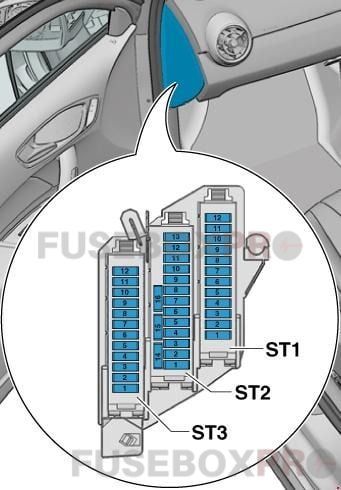
| No. | Amps | Assignment/Designation |
| Black | ||
| 1 | 7.5A | ESL control unit -J764- |
| 2 | 20A | Trailer detector control unit -J345- |
| 3 | 20A | Trailer detector control unit -J345- |
| 4 | 30A 7.5A |
Mechatronic unit for dual clutch gearbox -J743-, up to October 2014 Electronically controlled damping control unit -J250-, from January 2014 |
| 5 | 30A | Headlight washer system relay -J39- Headlight washer system pump -V11- |
| 6 | 5A | Interface control unit for vehicle location system -J843- |
| 7 | 7.5A | Entry and start authorisation control unit -J518- |
| 8 | 15A | Mechatronic unit for dual clutch gearbox -J743-, up to October 2014 |
| 9 | 20A | Sliding sunroof motor -V1- |
| 10 | 7.5A | Selector lever sensors control unit -J587- |
| 11 | 15 35)A | Engine component current supply relay -J757-, up to October 2014 Fuel pressure regulating valve -N276- , up to October 2014 |
| 12 | – | Vacant |
| Brown | ||
| 1 | 5A | Reversing light switch -F4- Selector lever sensors control unit -J587- Mechatronic unit for dual clutch gearbox -J743- |
| 2 | 10A | High-pressure sender -G65- Oil level and oil temperature sender -G266- Air conditioning system control unit -J301- Relay for power sockets -J807- Automatic anti-dazzle interior mirror -Y7- 16-pin connector -T16-, diagnosis connection |
| 3 | 5A | Data bus diagnostic interface -J533- |
| 4 | 5A | Heater control unit -J65- Control unit for structure-borne sound -J869- |
| 5 | 7.5A | Light switch -E1- Starter relay 1 -J906- Voltage stabilizer -J532- Starter relay 2 -J907- Relay for automatic anti-dazzle interior mirror -J910- Front left headlight -MX1- Front right headlight -MX2- |
| 6 | 5A | Light switch -E1- |
| 7 | 5A | ABS control unit -J104-, up to October 2014 Voltage stabiliser 2 -J570-, up to October 2014 Electronically controlled damping control unit -J250-, from January 2014 |
| 8 | 5A | Heated driver seat regulator -E94- Heated front passenger seat regulator -E95- Hazard warning lights button -E229- Heated rear window button -E230- TCS and ESP button -E256- Parking aid button -E266- Tyre pressure monitor display button -E492- Start/Stop operation button -E693- Trailer detector control unit -J345- Left washer jet heater element -Z20- Right washer jet heater element -Z21- |
| 9 | 5A | Power steering control unit -J500- |
| 10 | 5 36)A 7.5 37)A |
Air mass meter -G70- Fuel pump control unit -J538- Crankcase breather heater element -N79- |
| 11 | 5A | Airbag control unit -J234- Front passenger airbag deactivated warning lamp -K145- |
| 12 | 5A | Parking aid control unit -J446- |
| 13 | 5A | Control unit for headlight range control -J431- |
| 14 | 30A | Seat heating control unit -J882- |
| 15 | 15A | Rear window wiper motor -V12- |
| 16 | 5A | Engine control unit -J623- Air mass meter -G70- |
| Red | ||
| 1 | – | Vacant |
| 2 | – | Vacant |
| 3 | 10A | All-wheel drive control unit -J492- , gradual phase-out |
| 4 | – | Vacant |
| 5 | – | Vacant |
| 6 | – | Vacant |
| 7 | – | Vacant |
| 8 | – | Vacant |
| 9 | – | Vacant |
| 10 | 5A 10A |
Special vehicle control unit -J608- |
| 11 | – | Vacant |
| 12 | – | Vacant |
35) for models with 2.0 l petrol engine only
36) for models with petrol engine only
37) for models with diesel engine only
Relay/fuse holder F -SF-
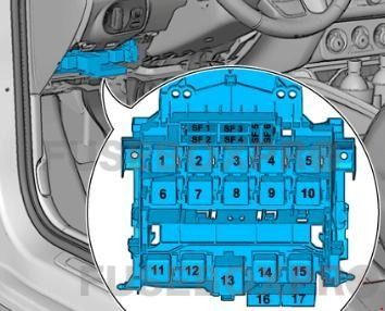
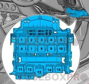
| No. | Amps | Assignment/Designation |
| 1 | 40A | Voltage stabilizer -J532- |
| 2 | 50A | Supply fuse carrier 1 -ST1- in fuse holder D -SD- |
| 3 | 40A | Terminal 15 voltage supply relay -J329- |
| 4 | 40A | ABS control unit -J104- |
| 5 | 5A | Voltage stabiliser 2 -J570-, gradual phase-out |
| 6 | 5A | Onboard supply control unit -J519- Voltage stabilizer -J532- Voltage stabiliser 2 -J570-, gradual phase-out Engine control unit -J623- |
| 16 | 10A | Brake light switch -F- (from November 2011, up to October 2014) Clutch position sender -G476- (from November 2011, up to November 2014) |
| 17 | 5A | Lambda probe heater -Z19- (from November 2011, up to October 2014) Lambda probe 1 heater after catalytic converter -Z29- (from November 2011, up to November 2014) |
Proper maintenance of the electrical components of the Audi A1 and S1 is essential for ensuring the longevity and reliability of these vehicles. Regularly checking and replacing blown fuses and malfunctioning relays can prevent larger electrical issues from occurring. Familiarizing yourself with the location and function of the fuse box and relay diagrams can help make troubleshooting and repairs easier for both owners and mechanics alike.