AMC Pacer fuse box and relay Diagrams (1975-1980)
The AMC Pacer is a compact car produced by the American Motors Corporation (AMC) from 1975 to 1980. It is introduced as a futuristic car with an innovative design that is unlike any other car at the time. Despite its unique looks, the Pacer is not a commercial success and is discontinued after just five years of production.
One of the notable features of the AMC Pacer is its electrical system, which included a fuse box and relay that controlled various components of the car. Let’s take a closer look at the electrical system of the AMC Pacer.
Electrical System
Fuse Box
The fuse box in the AMC Pacer is located on the driver’s side of the dashboard, just above the pedals. It contains a series of fuses that protect different electrical components of the car from damage due to electrical surges or short circuits. These components include headlights, taillights, turn signals, windshield wipers, and various other electrical systems.
The fuses in the AMC Pacer are color-coded, with each color representing a specific amperage rating. If a particular component of the car stops working, it may be due to a blown fuse. In this case, the corresponding fuse can be replaced with a new one of the same amperage rating to restore the electrical system’s functionality.
Relay
The relay in the AMC Pacer is a small electrical device that serves as a switch for various electrical components of the car. It is located in the fuse box and is responsible for controlling the power supply to components such as the horn, fuel pump, and electric fan. The relay works by using a small amount of electrical current to trigger a larger electrical circuit, which powers the corresponding component.
If a particular electrical component in the AMC Pacer is not functioning correctly, it may be due to a faulty relay. In this case, the relay can be replaced with a new one to restore the functionality of the corresponding electrical component.
(1975-1980) AMC Pacer fuse box and relay with Diagram
Type 1
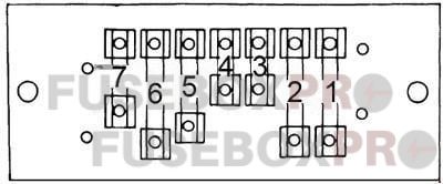
| No. | Amps | Assignment/Designation |
| 1 | 20A | Interlock module circuit, windshield wiper, park, tail, license, and side marker lights |
| 2 | 20A | Blower motor, air conditioner clutch |
| 3 | 4A | Interlock module circuit, headlight warning buzzer, oil light indicator, park brake, brake failure circuit |
| 4 | 4A | Panel illumination lights |
| 5 | 14A | Interlock module circuit, windshield wiper, park, tail, license and side marker lights |
| 6 | 20A | Stop light and hazard warning flasher |
| 7 | 9A | Dome, courtesy, glove box, trunk and cargo lights, clock |
Type 2
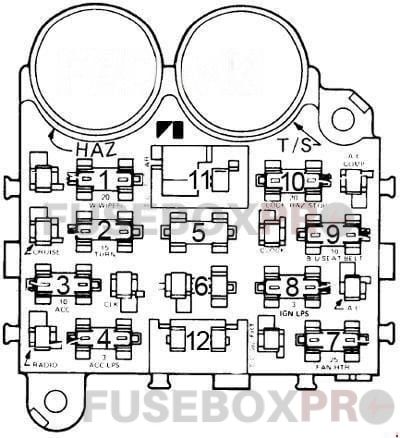
| No. | Amps | Assignment/Designation |
| 1 | 10A | Parking lights, key/headlight warning buzzer |
| 2 | 15A | Hazard warning, stoplights |
| 3 | 10A | Clock; dome and trunk lights |
| 4 | 3A | Cluster illumination |
| 5 | – | – |
| 6 | 10A | Radio, cigar lighter |
| 7 | 25A | Heater/A/C blower motor, A/C clutch |
| 8 | 7.5A | Gauges, Seat belt warning |
| 9 | 20A | Turn signals, backup lights, windshield washers |
| 10 | – | – |
| 11 | 30A | Power windows |
| 12 | 25A | Heated rear window |
Circuit Breaker:
- Headlights — 20 amp. the circuit breaker in the headlight switch.
- Windshield Wiper – 8.25 amp. circuit breaker for windshield wipers and 4.5 amp. breaker for the tailgate window wiper, both located at the left side of the brake support bracket.
- Power Windows & Tailgate Switches — 20 amp. circuit breakers located in the instrument panel.
The AMC Pacer may have been a commercial failure, but its unique design and innovative features make it a memorable car. The electrical system, which includes the fuse box and relay, is an essential part of the car’s functionality. Understanding how these components work and how to troubleshoot problems with them can help keep an AMC Pacer on the road for years to come.